3

I have an ATmega32u4 which I have configured to run its application by default at boot, and to run the bootloader (standard DFU USB bootloader from Microchip) when the reset button is pressed. I intend to use the bootloader for flashing the application using Atmel Flip.

I have the fuse bits set as follows:

fuse bits

And my reset circuit looks like this:

reset circuit

But, I found that this did not work - and the bootloader is always run at power-on instead of the application. This is a little baffling, but it gets worse...

I found that if I remove the 10 k pull-up (R441), it works as expected (the app runs at boot, and bootloader runs on manual reset).

Furthermore, I found that if I leave the 10 k installed but replace the 1 µF cap with 0.1 µF it also works.

And if I remove the cap altogether it works as well.

  • Fails
    • R441 - 10 k
    • C166 - 1 µF
  • Works
    • R441 - DNI
    • C166 - 1 µF
  • Works
    • R441 - 10 k
    • C166 - DNI
  • Works
    • R441 - 10 k
    • C166 - 0.1 µF

At first I thought the time constant with the 1 µF cap was too large, and the µController was reading the pin as a reset (active low) at boot, but that doesn't explain why it works when R441 is not populated. The ATmega32u4 has an internal weak pull-up, and using it alone would cause a much larger charge time.

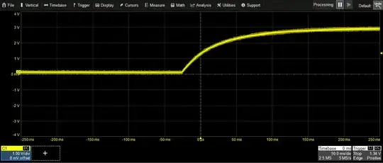
I can't find the value of the weak internal pull-up in the documentation, but I estimate it to be somewhere around 50 k, based on some oscope measurements:

Probe at TP87
With R441 un-populated (and 1 µF cap):

charge time with R441 DNI

With R441 (10 k) installed (and 1 µF cap):

charge time with R441 installed

I plan to go with the 4th configuration in my bullet points above (10 k and 0.1 µF), but I would love to understand why it is behaving this way. I would hate to find that it is working now, but fails to work later when fielded due to a new thermal environment or something.

Notes:

  1. The HWB pin is pulled to ground through a 10 k
  2. The HWBE and BOOTRST fuses are configured such that the application code should execute at boot unless external conditions apply: namely that reset is pulled low, sampled on the reset’s rising edge.
  3. The application itself has no calls to jump to the bootloader.

HWB description

enter image description here

enter image description here

Blair Fonville
  • 3,837
  • 4
  • 19
  • 45
  • PS. I have changed the value of R443 from 33.2 Ohms to 330 to be more in line with AN2519, but that doesn't affect the results, and doesn't really pertain to the question. Thanks – Blair Fonville Aug 26 '21 at 00:20
  • 1
    Please put your PSs in the question, you can edit your question. – Tyler Aug 26 '21 at 00:56
  • 1
    @Tyler well, as I said in the comment, it doesn’t really apply to the question, and all of my testing was done with the circuit as shown in the question. If it’s distracting, I can just delete the comment. – Blair Fonville Aug 26 '21 at 00:58
  • @BlairFonville you forgot to mention how do you determine between the two scenarios, reset rising up due to power being applied, or reset rising up due to someone pushing the button? How would the MCU know which case it is and what code to run based on it? – Justme Aug 26 '21 at 04:56
  • @Justme Thanks for the comment. It’s a function of the mcu to run the application code by default, unless external reset conditions apply, given the fuses as I have configured them (namely HWBE and BOOTRST). This is dependent on the HWB pin which I did forget to mention. I’ll had clarify remarks. – Blair Fonville Aug 26 '21 at 05:08

1 Answers1

1

I haven't used this particular MCU, but generally: never mess around with cap values on the /reset pin of any MCU. Pick what the manufacturer tells you.

In this case I can't find the recommendation in their datasheet, but 1uF sounds like a lot. This cap needs to suit the reset flanks and downtime of the part or you'll get very strange problems, if the cap starts affecting rise and fall times. Some parts need steep reset flanks.

It would appear that the intention here is to put a RC filter on the tact switch to de-bounce it. Makes sense, since a bouncing physical switch directly on the reset pin isn't a brilliant idea: you'll get spurious resets as well as ESD and EMI vulnerabilities.

If you can't get this working, then place something like a Schmitt trigger buffer IC in between the RC filter and the reset pin, so that the cap in the RC filter doesn't affect /reset. Move the pull-up so that it sits close to the pin. Many parts don't even need external pull-up nowadays.


Also in general terms: don't wave around /reset traces all over your PCB. On most boards, it's the single-most critical signal in terms of EMC. Why people keep insisting on putting physical switches directly on it, I have no idea. It's bad enough to expose it to some JTAG connector.

"It's good for debugging". Just find the reset button in your in-circuit debugger software and click on it with the mouse... or toggle the supply on/off.

Lundin
  • 17,577
  • 1
  • 24
  • 67
  • Thanks Lyndon. These are good notes. I agree with your comments regarding the signal transition, but the results seem to contradict the logic. Specifically, the fact that it works with 1 uF cap when the pull-up is not installed is bewildering. I.E. it works with the top oscope image, but not the bottom one. – Blair Fonville Aug 26 '21 at 22:46
  • Oh, and yes, my tact switch is located right next to the mcu and the trace is short. The reset switch is necessary. It won’t work as a soft reset. It’s not for debugging; it’s for jumping to the bootloader for flashing the chip. Power-cycle can’t substitute as a reset since the application runs at power-up, and the bootloader runs at reset. Thanks. – Blair Fonville Aug 26 '21 at 22:52
  • @BlairFonville Why would the bootloader need a power-on reset? That sounds unlikely. As I wrote, you could just use any GPIO for the switch then generate a watchdog reset. – Lundin Aug 27 '21 at 06:25
  • I’m may not have been clear, or I’m confused by “power-on reset”. We will fab the boards, kit, and assemble. The bootloader is preinstalled on the chips (they’re sold that way). But there is no application code (yet) to read gpios. The PWAs will be installed in the equipment we’re building. The reset switch and the ucontroller’s USB will be installed on the front panel. Pressing the reset tells the mcu to jump to the bootloader, which instantiates the USB. The USB is then used with Flip (software) for flashing the device. – Blair Fonville Aug 27 '21 at 06:40
  • @BlairFonville Sounds like it would have been _much_ cheaper to just buy the parts pre-programmed then. – Lundin Aug 27 '21 at 06:43
  • Once flashed the bootloader is no longer used, and only the application code is run. Whenever it’s turned on the app runs, not the bootloader. Sometime later use the bootloader again for firmware updates. But it never runs on its own. It will jump from the application code to the bootloader when the reset is pressed (not at power-on). – Blair Fonville Aug 27 '21 at 06:44
  • I don’t think it would be cheaper. We’re not mass producing anything. There may be 20 total deployed. – Blair Fonville Aug 27 '21 at 06:46
  • Having said all that, really appreciate the comments. It’s something to think about for future programs. And apologies for the typo in your name on my first reply! – Blair Fonville Aug 27 '21 at 06:48
  • @BlairFonville If it's just 20 then why don't you just flash them with an in circuit debugger then? – Lundin Aug 27 '21 at 07:46
  • The boards will be at the bottom of a stack of other cards and inaccessible. And the instruments will be assembled by another group before they’re delivered to me. But we’re kind of deviating from the original question a bit. I’d like to understand the behavior as I’ve described it for my own edification. But also, its too late for a redesign. Thanks. – Blair Fonville Aug 27 '21 at 07:52
  • @BlairFonville It's not rocket science to flash microcontroller at the point where you assemble the PCB... And it's not drifting from the topic since you've made an needlessly complex product design and the reason seems to be a lack of understanding of how electronics assembly/production is carried out practically. Making a product that can be easily produced is part of the EE designer's job too. – Lundin Aug 27 '21 at 08:25
  • The way it’s currently designed couldn’t be more simple. You plug it into a laptop, press reset, and upload new firmware. It’s so simple. Once delivered, firmware updates will need to be done by people who know nothing about electronics. As stated in my question, it works perfectly in 3 of the 4 bullets I listed. My question was only to ask why it doesn’t work for the 1. I fail to see where it is needlessly complicated. This is a standard usage of the microcontroller. – Blair Fonville Aug 27 '21 at 08:29
  • @BlairFonville Except your solution makes the microcontroller unreliable and therefore the whole product unreliable... that's what I mean with needlessly complex. You could just remove everything from the reset pin, provide a flash connector, flash down a bootloader upon manfacturing, done. – Lundin Aug 27 '21 at 08:36
  • It’s not unreliable. Again, it’s a standard usage. This is an intended feature of the microcontroller. No extra hardware necessary for the end user. And very little front panel space is needed with a micro USB port. – Blair Fonville Aug 27 '21 at 08:39
  • The USB capability of the mcu is built in expressly for this purpose, which is why they are sold with the bootloader preinstalled, and why they provide the free software (Flip) for uploading via USB. It’s really quite simple. I was impressed. – Blair Fonville Aug 27 '21 at 08:43
  • @BlairFonville Okay so it is working fine after all. Nice, ship it. – Lundin Aug 27 '21 at 08:55
  • Yes, it is working (I stated that in my question), which is why I think we’ve gotten a little off topic. I always try to find the solution before asking my questions. Your comment reads a bit snarky. I hope I haven’t offended. If I have, it wasn’t my intention. – Blair Fonville Aug 27 '21 at 08:56