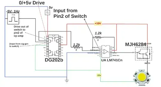
I've designed the following circuit in order to control a 12V fan with PWM. The circuit is meant to stay at a fixed frequency of around 25kHz but a variable duty cycle controlled by a potentiometer.
The circuit behaves just as per the design goals in LTspice. In this simulation, R6 and R8 represent the potentiometer.
I have now built the circuit on a real PCB and I have the following issues:
- The PWM frequency not as per the design. This is probably because of components tolerances. To get a frequency closer to 25kHz, I need to change C1 to 82pF
- The PWM frequency is not constant. This is quite problematic. At 25% the frequency can be as low as 21kHz and then at 80% around 29kHz. The fan I am using needs to be fed with a constant frequency, otherwise it "resets" so the increase/decrease of the fan blades rotational speed is not smooth as one would like it to be.
Note that the real PCB has some extra capacitors and a ferrite for decoupling and 12V filtering.
Do you see any problems with my circuit or have a recommendation to fix the problem with the frequency shifting up and down from its designed set point?

