0

I have the conductance and susceptance vs. grequency data on an acoustic transducer. Also mentioned is the resonant resistance and resonant capacitance which is just the inverse of the conductance and susceptance value at the resonance frequency.

The given data is:

  • Resonant Frequency(fc) = 44000Hz
  • Conductance = 6963.4 uS
  • Susceptance = 4307.73 uS
  • Resonant Resistance = 143.61 ohm (= 1/Conductance)
  • Resonant Capacitance = Susceptance/(2 * pi * fc) = 15.581 nF

From the conductance and susceptance are given, if I calculate Y=G+jB and then Z= 1/Y or R = G/(G^2+B^2) and X = -j * (B/(G^2 + B^2)), I am getting different results than the resistance value mentioned in the data provided along with the transducer.

Am I missing something or calculating incorrectly?

If I am not wrong, R=1/G is only applicable when there is no reactance or susceptance.

JRE
  • 67,678
  • 8
  • 104
  • 179
pp123
  • 1
  • 1

2 Answers2

0

schematic

simulate this circuit – Schematic created using CircuitLab

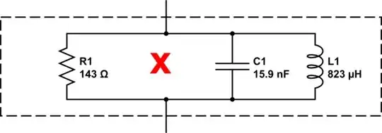
When you see "resonating capacitance = 15nf", there is implied an associated resonating inductor. The capacitor and inductor combine to resonate at 44000 Hz. It is very unlikely that C1 and L1 and R1 are actual physical components.

I'm assuming that "Resonant resistance" is in a series circuit, since a parallel resistance with that capacitor describes a network that is not particularly resonant:

schematic

simulate this circuit


So which is it...

  • a parallel "resonant" circuit?
  • a series resonant circuit?
  • or something more complex?

You gain some more insight by measuring with DC, as an ohmmeter does.

As for something more complex, consider the simplified model (below) for a loudspeaker transducer. It does display a resonance at low frequency, yet an ohmmeter will measure about 6 ohms. Note that this model is incomplete - at higher audio frequency, this model deviates from reality. And the elements that convert electrical energy to acoustic energy are missing.

schematic

simulate this circuit

Another "more complex" model of a resonant transducer is sometimes used to describe a piezo-electric ceramic element:

schematic

simulate this circuit

In this case, resonance usually describes the series arm of R1, C2, L1. A measurement of transducer reactance at a much lower frequency than resonance gives a capacitive susceptance dominated by C1. C1 > C2....for the piezo properties of a crystal, the factor might be 100 - 250.


TLDR: The simple series circuit (top of answer) is the more likely model - a slightly resonant series circuit. Be aware that this simple model needs many more elements to properly describe how your acoustic transducer outputs acoustic energy from electrical energy.

glen_geek
  • 23,591
  • 1
  • 22
  • 50
0

When dealing with acoustic transducers, admittance is the customary units since the working bandwidth is readily seen in the conductance versus frequency plot. It is implied that admittance data for acoustic transducers are parallel components. Your transducer model in parallel and series formats at 44kHz looks like this:

schematic

simulate this circuit – Schematic created using CircuitLab

As you stated, \$ Z = {1 \over Y} = 103.9 -j64.3 \$ which is how you go from the parallel topology to series topology. If you're trying to tune out the reactive part of the transducer because you are using the transducer as a projector, the series topology is easier to work with since you will choose an inductor with the same inductive reactance magnitude as the capacitor, or \$ L = {X_L \over \omega } = 233 \mu H \$. If you add a series tuning inductor, you will get a voltage gain at resonance of \$ \sqrt{1+ {\left({X_c \over R}\right)^2}} \$.

The series topology is also convenient for figuring out the thermal noise of the transducer since that is the noise caused by the real part of the reactance, or about \$ 0.13 \,\sqrt{103.9} \approx 1.3nV \$.

qrk
  • 7,474
  • 1
  • 5
  • 20