3

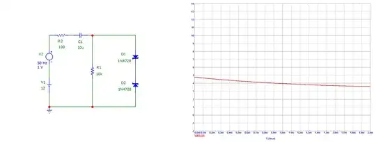
I have this test circuit, which has this signal: enter image description here
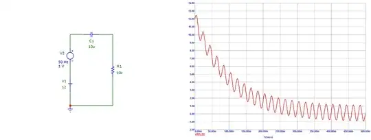
V1 may change from 1 to 30 V, V2 may change from 0 to 4 V peak to peak. I need to clip the signal at about 3 - 4 V to feed it to an Op Amp, which has a split supply voltage of about -5 and +5 V. So I added two zener diodes and the signal was clipped: enter image description here
But it was not fast enough, for about 300 microseconds the signal was still above 5 V - the Op Amp power supply voltage, which, I figure, may damage the Op Amp: enter image description here
How can I clip the voltage faster, without distorting the signal that is below 3 - 4 volts?

Update: If anybody is interested, here is the analysis with a series resistor, as Andy aka has proposed below in his solution: enter image description here enter image description here
  • Use the fact that you have 2 V overhead to play with, prebias a Zener diode to whatever clamp level you desire and make an active clamp? – winny Aug 16 '21 at 07:18
  • Could you please elaborate? How can I realize that without disturbing the signal I want to measure? – Thomas Anderson Aug 16 '21 at 07:24
  • @ThomasAnderson I'm a bit confused – what is the thing you want to measure, precisely? – Marcus Müller Aug 16 '21 at 08:00
  • @MarcusMüller I need to measure the max. amplitude of V2 (the ac component). – Thomas Anderson Aug 16 '21 at 08:33
  • Depends. How much is "without disturbance"? I started to draw an emitter follower for you, but by that time you might as well throw in an unity gain opamp with +- 3 V supply which has good recovery from overvoltage on the input. Then again by that time, can't you just swap the opamp you are feeding into? – winny Aug 16 '21 at 09:32
  • winny, I have no idea what you are talking about. – Thomas Anderson Aug 16 '21 at 11:54
  • I'll try to re-phrase. I sense an XY problem. Your opamp is fed by +-5V, but cannot accept the full common mode voltage on the input. This is common. You want to go around the problem by clamping the input to avoid that situation. This is an XY solution to your problem. Are you allowed the change the opamp in your design? If yes, why can't you just choose one which is rail-to-rail on the input and can accept the full +5 to -5 V range? If your signal is outside of that, there are opamps which can survive that too. – winny Aug 16 '21 at 13:07
  • So, you think that a better workaround to the problem would be to use a different Op Amp instead of clamping. Maybe you are right. Which Op Amp would you recommend for the given task (input up to 32 V, power supply +5 and -5 V)? – Thomas Anderson Aug 16 '21 at 13:52
  • Maxim MAX4163 or similar (you’re at the Vsupply limit here), probably with series resistors on the input to limit the current. – winny Aug 16 '21 at 20:10
  • Thank you for suggestion, winny. I will need a high slew rate Op Amp, but your comment is helpful, I will keep it in mind. – Thomas Anderson Aug 20 '21 at 04:11

1 Answers1

1

You don't have any current limiting resistors. Even 1 ohm would help alleviate the problem of big currents flowing through C1 into D1 and D2: -

enter image description here

Clearly, the bigger that added resistor is the better the situation is. You might be able to get away with 10 Ω of course. Maybe you should also add a 1 kΩ resistor in series with your op-amp input - this will prevent input current overload into your op-amp too.

Andy aka
  • 434,556
  • 28
  • 351
  • 777
  • Andy aka, you are right, some protection will be needed. But in this test circuit the zeners have a dynamic resistance of about 10 ohms each, in series it's 20 ohms. At 12 V this gives about 600 mA for a short time of some microseconds. The zeners are rated to withstand surge current of 1380 mA. How did you calculate hundreds of amps? About the Op Amps inputs, I thought they do not draw that much current. Could you please explain the role of that 1k resistor? – Thomas Anderson Aug 16 '21 at 08:45
  • You are using micro-cap so plot the current surge into those zeners. You might find that they are not modelled as exactly as you think. Always double check models is a rule for me. Of course I may be mistaken. When the input voltage rises above the supply rail on the op-amp the input takes current so, adding the resistor reduces that current to acceptable levels. – Andy aka Aug 16 '21 at 09:00
  • Andy aka, transient analysis gives that the current through zeners drops from about 425 mA (maximum value) to about 6 mA in 1 millisecond. Of course, in reality it will be different, but maybe not that much. Thanks for the hint with an input resistor. Is there any way to make sure that it will save the Op Amp from burning out? – Thomas Anderson Aug 16 '21 at 09:15
  • 1
    OK 425 mA sounds about right now I've looked at the zener data sheet and calculated the peak voltage based on the dynamic resistance; if you want improved clamping go for a series resistor as I mentioned or use beefier zeners. Regarding the input resistor, the op-amp data sheet will usually indicate how much current you can safely push into its input. So, if it says (say) 5 mA then you should aim not to push anything more than 2.5 mA into your input pin. Given that your op-amp might be powered from 5 volts you basically have 7 volts across the resistor. So, 7 volts / 2.5 mA = 2800 ohms. – Andy aka Aug 16 '21 at 09:31
  • Thank you! I was sceptical about this series resistor, but did the analysis and it worked! As to the inputs current. I found an absolute maximum rating for input current in only one datasheet, it is 5 mA indeed, but the datasheet says: "This input current only exists when the voltage at any of the input leads is driven negative". So, I am assuming that this rating is for the current driven out of the Op Amp. Is it valid to assume that the same rating is applicable to the current driven into the Op Amp by the input overvoltage? Semiconductors do have different ratings for opposite directions. – Thomas Anderson Aug 16 '21 at 13:18
  • Dunno - link to the datasheet and what page @ThomasAnderson – Andy aka Aug 16 '21 at 13:19
  • Here is the link: https://www.st.com/resource/en/datasheet/lm158.pdf page 3 – Thomas Anderson Aug 16 '21 at 13:26
  • 1
    The LM158 uses a Darlington PNP transistor at its input and so should be able to live with an input voltage that is about 10 volts higher than its positive supply voltage but, it's an old crusty device and the data sheet details are a bit scant on that part (and the TI part) so, after the current limiting resistor I'd add a diode that goes from the input pin to Vcc of the chip just to be cautious. The TI datasheet also says this: *Inputs may exceed VS up to the maximum VS without device damage* (quite a useful bit of help). The devil is in the detail and it's worth checking other suppliers. – Andy aka Aug 16 '21 at 13:44
  • Thank you again. I had the Texas Instruments datasheet opened, but have not noticed that bit. I ran the analysis with the diode and the series resistor on the input - it works well. – Thomas Anderson Aug 16 '21 at 15:23