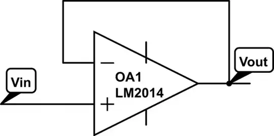
I have some simple experience with TTL logic and Arduino, but I'm only a hobbyist and am bit stymied by my current project, which is attempting to read the data from an old Intel 1702A EPROM. The actual reading part should be simple: set the address lines and look at the data lines.
But this EPROM wants both +5 V (Vcc) and -9 V (Vdd, Vgg) supply voltages in its read mode. (Here's the data sheet.) I have a DC supply that can give me +9 V, which can power the Arduino and as a nice side effect creates a +5 V supply at the Arduino that I can then use for the EPROM's Vcc, but I'm stuck on how to find a minus 9 V supply, such that the Arduino logic and the 1702A are all relative to each other correctly.
I know this is not an advanced question, but I'd appreciate some guidance. I know I can't simply take the ground connection on the power supply (which is -9 V relative to its positive terminal) because it's not correct relative to the +5 V Vcc on the chip.
Can someone point me to some simple setup (voltage divider? zener diodes? or?) that I can use to end up with the -9 V? If my DC input needs to be something other than +9 V to make the difference work, then let me know, and I'll need to power the Arduino somehow too.
Thank you!
