I have a 28V digital signal. 28V being logic 1 and 0V being logic 0.
Can I feed the 28V into an opamp (Vcc @5V) to level shift it ? Or will I have to create a voltage divider to bring the 28V < Vcc ?
I have a 28V digital signal. 28V being logic 1 and 0V being logic 0.
Can I feed the 28V into an opamp (Vcc @5V) to level shift it ? Or will I have to create a voltage divider to bring the 28V < Vcc ?
Direct feed isn't going to work well for you.
You'll find that the common-mode input range of an opamp is quite often less than the supply voltage rails (less than VCC, greater than VEE) . Some parts (those with rail-to-rail inputs) can accept signals at the same potential as the supply lines.
Usually there are p-n junctions between the opamp inputs and the rails (sometimes deliberate, often parasitic) which can forward-bias and fry if a stiff signal higher than the postiive supply or lower the than negative supply is applied.
Current-limiting the source will cause the voltage at the input to clamp a diode drop above or below the rail (depending on polarity) but there's no guarantee the rest of the opamp will behave nicely in this condition.
Although in this case it's probably much simpler just to use a voltage divider, I'd like to point out that this can be done.
With an inverting opamp, you can do this. Since the output drives the opposite way to the input, you can make use of this to compensate (work against) the input voltage and make sure the inverting input does not see a higher voltage than it's supply. Using the correct ratio of Rin and Rf, you can adjust the gain as necessary. If it's a DC input, you need to compensate for this at the non-inverting input though.
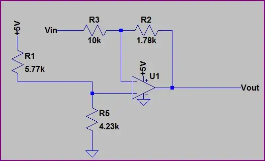
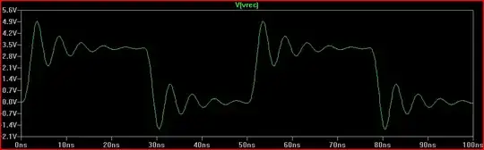
This maybe better explained with an example circuit (note that a rail to rail output opamp stable at all gains is required). This takes a 28V pk-pk waveform (i.e. -14V to +14V) and outputs a 0-5V waveform (so we have an input voltage that exceeds both rails):
Simulation:
How do we calculate R3 and R2?
This bit's easy, we just need a gain of 5/14 = 0.178. If we have a 10kΩ Rin (R3), we can use:
10kΩ * (5 / 28) = 1.78kΩ
What about R1 and R5?
We know that when the input is at +14V, the output should be at 0V. Using this info and knowing that no current flows into the non-inverting input, we can treat R3 and R2 as a voltage divider. Since the opamp will try and make the inputs equal, we need the non-inverting input to be the same as the voltage at the non-inverting input at this point.
So let's work out the voltage at the non-inverting input:
14V * (1.78k / (10k + 1.78k)) = 2.115V
So wee just need to apply 2.115V to the non-inverting input to compensate and shift the output voltage. Using the +5V supply and a voltage divider:
2.115V / 5V = 0.423 - this is the ratio we need.
So R5 / (R5 + R1) = 4.23k / (4.23k + 5.77k) = 0.423 and:
5V * (4.23k / (4.23k + 5.77k)) = 2.115V
How to calculate for various configurations, and much more is discussed in Opamps for Everyone, a good free book from TI.
You need a voltage divider. Putting signals larger than the span of the power pins on the op amp inputs can cause permanent damage to the op amp.
I have asked the same question here previously.
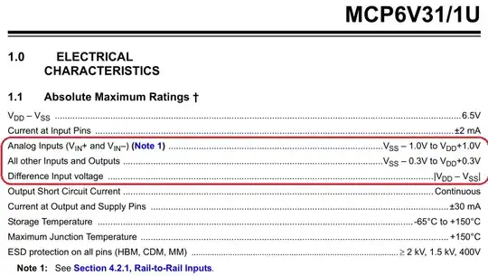
Later, I learned that the datasheet already gives this information.
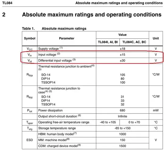
Open the datasheet of your opamp. Find the table in which "the absolute maximum ratings" are listed.
Example #1:
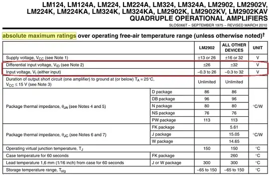
Example #2:
Example #3: