1

With no application in my mind, I am playing around the circuits and came up with some doubts. I asked a question in Current sinking in a DC-DC module to which I received the answer. However, I got curious and came up with another doubt.

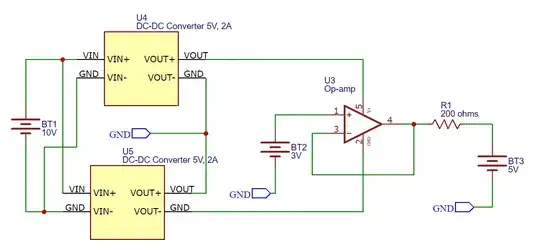
If I connect the following circuit, will the op-amp do the magic? In this circuit, I am connecting the modules in series to power an Op-Amp. The op-amp out is connected such that it needs to sink 1A to maintain the 3V at its output. In this configuration, I have the following questions.

  1. Will the op-amp be able to sink the 1A?
  2. If the op-amp sinks 1A, will it force the power source to sink or it will act as a load to the power source?
  3. Is it even valid to use such a circuit electronically? If not, what are the reasons?

Power modules powering an op-amp

SKGadi
  • 862
  • 3
  • 13
  • 1
    Valid, but 1A is too much, source or sink. Maybe a couple mA. Remember, opamps are linear devices like linear regulators = heat. Adding output transistors will source and sink much more. The power source only sources or sinks at its own voltage (if it was even designed to sink); That's why it is a source. The voltage difference between sink or source voltage and the powr source has to appear somewhere. – DKNguyen Aug 04 '21 at 14:56
  • 1
    Is that DC-DC converter isolated? If not you can't just connect the positive output of one to the negative of the other. – Unimportant Aug 04 '21 at 15:10
  • @Unimportant, Yes, these are isolated power modules – SKGadi Aug 04 '21 at 15:19
  • @DKNguyen, Are you suggesting something similar to this circuit? https://circuitdigest.com/sites/default/files/inlineimages/u2/Voltage-Controlled-Current-Sink.png I am taking this from the website: https://circuitdigest.com/electronic-circuits/design-a-simple-constant-current-sink-circuit-using-op-amp – SKGadi Aug 04 '21 at 15:27
  • whoever told that DC converters dont sink current is wrong: They sink into their negative output. A single DC converter is thus enough. – tobalt Aug 04 '21 at 16:37
  • @SKGadi Sort of. To both sink and source you need a two (complimentary) transistor push-pull arrangement. Not just one transistor which only sinks or sources. – DKNguyen Aug 04 '21 at 17:31
  • Technically, the opamp circuit is not asked to sink current, but to maintain it's output at 3V. If the goal is to sink a perdetermined current, then the opamp circuit topology has to be different. Generally the OPAMP is not able to sink 1A. You'll need to add one or more transistors and or mosfets with a suitable heatsink to be able to continuously do so. If BT3 stays within -5V to 5V bounds, your OPAMP will not sink more than 10mA and have to drive at most 40mA. This circuit can help determine how a battery/cell behaves under a constant 3V load with a 200Ohms internal resistance. – le_top Aug 04 '21 at 22:39
  • @le_top , Do you have example circuit with BJT or FET that does the operation of maintaining 3V while the 1A passing through transistor instead of op-amp? – SKGadi Aug 05 '21 at 12:51
  • @DKNguyen, do you have an example circuit to the push-pull arrangement for this purpos? – SKGadi Aug 05 '21 at 12:52
  • http://www.ecircuitcenter.com/Circuits/pushpull/pushpull.htm – DKNguyen Aug 05 '21 at 13:53

3 Answers3

3

If you do that to a typical op-amp (say, an LM358,) then you will "release the magic smoke" - destroy the op-amp, that is.

Op-amps must be able to source and sink current to operate. They aren't normally designed for large currents, though.

Typical op-amps work in the area of a few milliamperes. Forcing 1A of current through them is a good way to destroy them.

Something like the TI LM675 or the Analog Devices LT1210X could sink that 1A, and live to tell the tale - but they are not your typical op-amp.

If you respect the current limits of your op-amp then they can sink current without damage.


In the example you give, the 200 ohm resistor and the 1A current source will "look like" a load to the negative 5V power supply.

JRE
  • 67,678
  • 8
  • 104
  • 179
  • With your reply, I understand that this circuit is theoretically possible, but we have practical limitations because of the high currents. I have the doubt: Which source will consume the energy for the heat generated in the op-amp? The U5 DC/DC module or the BT3? – SKGadi Aug 04 '21 at 15:26
  • The op-amp will consume the energy used to heat it. The current flows through its output, through the negative supply pin, to the negative power source. – JRE Aug 04 '21 at 15:27
2

Firstly, in your circuit, the opamp is not being asked to sink 1A, the current is:

I = (5V - 3V) / 200Ω = 10mA

Almost any opamp is capable of sinking that current, and nothing will be damaged.

Let's assume that the opamp is an LM358, and that R1 = 2Ω, in which case you are certainly over-loading the opamp.

According to this datasheet, the short circuit current (to ground) is typically 40mA maximum, and while there's no mention anywhere of short circuit current while sinking, I will assume a similar limit in that case also.

This answers your first and second questions "can/if the opamp sinks 1A..." - an LM358 can't, and it won't.

Due to its inability to sink or source 1A, the opamp cannot hold its output at 3V under such a load, which may thus be considered a "short-circuit" in this scenario. I'll assume that the resistor wins, clamping the opamp's output close to 5V.

The opamp's lower output transistor (the one responsible for sinking current) has a voltage across it of 5V - (-5V) = 10V, and at 40mA it will be dissipating 10V x 40mA = 400mW.

The datasheet (page 4, "Absolute Maximum Ratings") tells us that the maximum power that may be dissipated is somewhere between 435mW and 830mW, depending on the packaging. So while we are certainly abusing the device, it will probably survive, even if the abuse continues indefinitely.

Damage could occur if the power supplies were larger (say ±10V), but hopefully you can see why abuse, up to some point, may be perfectly tolerable.

However, there are opamps that are quite capable of driving a 2Ω load, such as the OPA569. If you employed this device in your circuit, it could easily maintain an output of 3V, and sink the entire 1A of current that would result.

You would still be concerned with power dissipation, because it is now:

P = 1A x [3V - (-5V)] = 8W

You would need some serious heat sinking and air-flow to give the thing any hope of surviving for more than a few seconds under these conditions, but you can see why the answers to your questions really depend on what opamp you are talking about.

To address your third question "is this a valid circuit, with valid applications", yes, and no. You can't drive a 2Ω load with an LM358, but you can with an OPA569. And of course there are applications where the load is a current source, which the opamp must sink.
Simon Fitch
  • 27,759
  • 2
  • 16
  • 87
1

Here's a quick hand-drawn partial schematic in response to your question in your comment : "Do you have example circuit with BJT or FET that does the operation of maintaining 3V while the 1A passing through transistor instead of op-amp?" .

Partial schematic to maintain 3V on output (at the emitter junctions)

The 200 Ohm resistor is drawn only with reference to your original schematic: it's too big to allow 1A.

You an replace it with a smaller resistor and feed back into the '-' pin at the other side of the resistor to maintain 3V there, while limiting the maximum current.

The PNP and NPN do not add gain to the open loop, so the stability of the opamp is not detoriated. They need heat sinks to dissipate 5 to 10 Watts. You need to check the "beta" (current amplification) of the NPN and PNP as well and check that the opamp and drive/pull the required current. This can be improved with biasing circuitry, a darlington, etc. In a first order approach, you probably can get away with such a simple circuit.

This is of course a circuit to show how you can adjust the original one. There are standard (fixed and variable/"programmable") cheap and performant voltage regulator components that can drive high currents and regulate towards a fixed voltage. However most regulators expect a load, not a power source on their output and I do not expect them to be able to draw power. You could add a load of 3 Ohm (cooled) on the regulators output which would always draw 1A at 3V and let the regulator add the extra current that is needed to maintain the output at 3V with regards the current already coming from the output.

le_top
  • 3,111
  • 11
  • 22