3

I'm quite new in electronics, but I'm not scared to try it (Look Mum No Computer). So please bear with me and tell how to improve my asking.

I am building a guitar pedal. It's a op-amp based parallel effect loop with boost controls for each channel. These are controlled digitally by an Arduino. And yes, it might sound like a wild beginners project, but I don't mind the project moving veeery slowly. And I'm currently a the point where all programming is done (and working), and I'm tinkering with the analogue parts.

My challenge now is to get the power I need.

For the op-amps I would like to use 18V (+-9) for a bigger amount of headroom. I use a TL074 to split, buffer and boost the audio signal. Later in the chain I will have a TL071 op-amp to boost the mix. Sometime later I'll maybe add in a TL072 for phase shifting possibilities.

Currently using an Arduino I can feed it 9V though the VIN input, but in the long term I would love to use a standalone circuit with the ATMega328 chip. Therefore I need to think the 5V into the power circuit.

Here's what I've tried:

Firstly tried dividing my 9V input with a resistor divider giving me +-4.5V. When measuring, the negative volts looked just right, but using it through an op-amp it went out of balance causing the sound to overdrive an make ugly clicks. My cheap oscilloscope showed me beautiful waves on the upper (+)side and ugly cut off waves on the lower (-)side.

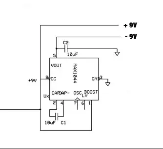
Then I found the ICL7660/MAX1044 chip and made a circuit to double the voltage supply to +-9V, using this schematic:

enter image description here

The measuring looks fine, although not giving me +-9 but +-8.1 using a 9V battery. Putting it through the op-amp circuit it sounds a lot better! No clicking and overdrive not as present. This is probably due to the larger headroom. But using a sound generator and oscilloscope, it shows me that this supply is also moving out of balance. The negative waves are cut half. And the power supply is no longer +-8 but more like +12/-4. How can I get a stable dual voltage supply?

Regarding the extra 5V. I can get beautiful 5V by adding a LM7805 converter to the input 9V, but I am unsure if this is the best way to do it. It has no visible effect on the output of the ICL7660.

How would you do it? How to get a stable +-9V plus a 5V from a 9V DC source? It doesn't have to run on batteries, a DC adapter will also do.

I would love if there was a relatively simple solution that doesn't require a lot of space ;)
Here is a current oscilloscope shot: enter image description here

  • Have you made an "evaluation" of the power needed for all voltage sources ? – Antonio51 Jul 29 '21 at 17:59
  • In the analogue circuit I will use a total of seven op-amps consuming a maximum of 2.5mA each. The digital circuit is way bigger counting an arduino, 9 leds a 7 segment display and three multiplexers. But you mean for the analogue circuit, right? – Jesper Kragh Jul 29 '21 at 18:08
  • Unless digital part powered separately, through a smps 9V -> 5V or 3.3V ... – Antonio51 Jul 29 '21 at 19:04
  • Right now the digital part is totally separated (on a different board, with its own power supply). My main concern is to make the analogue part and its op-amps working correctly, meaning no cutting off the negative waves. – Jesper Kragh Jul 30 '21 at 07:18
  • " The negative waves are cut half. And the power supply is no longer +-8 but more like +12/-4. How can I get a stable dual voltage supply? " . It seems that icl7660 may be paralleled . Have you tried this ? – Antonio51 Jul 30 '21 at 10:32
  • You can almost certainly do OK with single 9B supply with rail to rail opamps, but unless you particularly want to build your own a cheap premade module may suit.|| If DIY then an inverting inductive smps may be easiest. So called inverting buck boost can be done by a range of smps ics.more if wanted. – Russell McMahon Jul 30 '21 at 12:39
  • Use 2 9V batteries in series. Where they connect is 'ground'. The other terminals are then + and - 9V. Easy – Kyle B Jul 31 '21 at 04:28

3 Answers3

4

The MAX1044 appears to only be capable of sourcing 20mA. Depending on the load requirements of devices on the -9V supply, this may not be adequate and be the reason for drooping voltage on that net.

Another solution may be to use 2x 9V batteries connected in series, with their common connection used as your circuit ground, and their other 2 leads being your +/-9V nets. However, it's worth considering in this case and in your current implementation that the battery voltage will droop dependent on the current draw, as well as dropping over its discharge range.

Depending on your +5V requirements, the simplest solution may be a Low Dropout linear regulator. They are very easy to use, and are not noisy, which may be an issue in audio circuits. With these regulators, you need to be careful of the power dissipated across them, which is calculated as the dropout voltage (Vin-Vout = 4V) times the load current. If your +5V load is reasonably small, an LDO would work well. To avoid issues, you can also use LDOs in packages that easily dissipate heat away from the device.

Unfortunately I can't comment on posts, but I see another user pointing out limitations in the negative output range of the TL07x OpAmp. I'm failing to find the -4V limitation in the datasheet, and am seeing that the output can go reasonably close to both rails, depending on the supply voltage, load, temperature, and exact version of the device use. Although I don't think the output at +-9V is that limiting, it's still something to consider in your design.

Christian
  • 138
  • 9
  • So you mean +-9V is too little still? I can't find the -4V limitation either. – Jesper Kragh Jul 29 '21 at 18:38
  • What is your intended output range of the OpAmps, is really the question. Unless you use a "rail-rail" OpAmp, your output is never going to reach the full supply voltage range of +/-9V, and your waveform will be distorted if you try to drive it beyond the limitation. I also forgot to mention in my original response, which I will add now, that drawing current from a battery results in a drooping output voltage proportional to the load and battery capacity (check out 9V battery discharge curves online). – Christian Jul 29 '21 at 18:42
  • I would actually like to avoid batteries and use a 9V DC adapter, since it is what available on my pedal board. – Jesper Kragh Jul 29 '21 at 18:42
  • No, the output range does not have to be that big at all. I'm mostly interested in centering the wave, so it doesn't cut one side. I can easily change the amount of gain by changing one resistor. – Jesper Kragh Jul 29 '21 at 18:45
  • Well the easiest way to do that is just to bias your OpAmp output to 9V/2, which allows an output swing of almost +/-4.5V (depending on how close it can drive to the rail). I'm not super familiar with how guitar pedals are constructed, but this may not even need an onboard regulator if the 9V external DC supply is low tolerance and not too noisy. Also, I know sometimes pedals are chained on a single board with a common supply, so you may want to look into how other pedals are constructed, and if this will cause compatibility issues. – Christian Jul 29 '21 at 18:55
  • I also highly suggest you simulate these circuits with LTSpice. You can typically simulate with exact parts, and these simulations are relatively accurate and allow you to learn a lot, similar to hands-on work. – Christian Jul 29 '21 at 18:57
  • My op-amp are biased to swing 18V/2 for better headroom. There is a possibility that the pedals added before or in the effect loop will have a high output, so I need the space. But a stable division to +-9V would be nice. – Jesper Kragh Jul 29 '21 at 19:48
3

The ICL7660 is very useful if you don't need to draw much current from its output.

From the Renesas datasheet There's this graph (page 5):

enter image description here

As you can see, as soon as you start to draw any current from it, the output voltage rises (becomes less negative) quite quickly. They even calculate the effective output resistance for you, 55Ω!

At 35mA you've already lost 2V. The TL072 and its variants are great things, but they have trouble getting their outputs closer than 1.5V or so to either supply rail, so that's a total of 3.5V of negative supply gone, leaving only 5.5V of negative output swing. On top of that, opamps generally won't do what you expect if either of their inputs falls outside the supply voltages, which becomes more and more likely as the negative supply diminishes.

The ICL7660 starts to look a little inadequate for anything except applications demanding less than a few milliamps.

It's been suggested here that you use a second 9V battery to provide the negative rail, and this is indeed what many people do, as a quick and easy solution to your dilemma. Just be aware that the two batteries will not deplete their charge at the same rate, which I always found to be "ugly" - I've never been happy not knowing which of the two batteries is dead, and needs replacing. Just a personal thing.

The third option I would encourage you to explore is to either build your own DC-DC converter to obtain the negative rail, or buy a prebuilt module, such as this one (from ebay).

If you fancy having a go at making one yourself, ICs you might consider are LT3483 or MC34063 (which is the one used in the ebay module above).

The main benefit to you in going this route is that you obtain a stable negative output voltage, even under loads of hundreds of milliamps. You may have to take care to filter this voltage source, as DC-DC converters are noisy, but that's another story.

To address your question about the 7805, this is a perfectly reasonable approach to obtaining 5V from a 9V source. It's somewhat inefficient, but since your current requirements are low, this is of little concern. It's a tried-and-tested way of doing things.

Simon Fitch
  • 27,759
  • 2
  • 16
  • 87
  • Cool! I would love to see a schematic of a MC34063 or LT3483 DC-DC converter that takes in 9V and lets -9V out. I can't figure that out myself and I'm having trouble finding the right example. I'd like it to be small and quiet. I won't need current draw beyond 100 mA. – Jesper Kragh Jul 30 '21 at 16:24
  • @jesper kragh there is a large MC34063 application note that gives many applications. Advise me if you cannot find it. – Russell McMahon Jul 31 '21 at 06:49
  • Simon and @RussellMcMahon, Thanks! I've been searching a little on using MC34063 for op-amps in audio applications and haven't really found anything. The ICL7660 and Rail-splitters are common, though. Found this https://www.diyaudio.com/forums/chip-amps/206788-using-2-mc34063-cmoy-virtual-ground.html, - which made me a little concerned. I'm not after getting exactly +-9V just something stable beyond the +-4.5V. It seems my biggest problem could be the current draw, but how much will actually draw using 5 op-amps in a super simple circuit. – Jesper Kragh Jul 31 '21 at 10:33
  • @JesperKragh 1mA per opamp won't put much of a dent in the voltage, but the loads they are driving (including their own feedback) might. Maybe as opamp output rises and sources current, those signal peaks could emerge as ripple on the negative supply, especially at lower frequencies. Not sure though. – Simon Fitch Jul 31 '21 at 12:25
2

There are numerous inductor based SMPS (switch mode power supply) ICs that will provide step down or step up or inverted polarity supplies.

An IC which is very old and not as efficient as many more modern ICs (unless designed with great care) but which was designed to be immensely flexible and which is about as low cost as any is the MC34063 and variants. [I have used several hundred thousand of them. [In these bit.ly/SL2MINIAFRICA - scroll with mouse wheel]. In volume in China, they cost a few cents US each. Despite their age, they can still produce acceptable results in many applications.]

Here is OnSemi AN920D - a 43 page application note devoted to the use of the MC34063. It shows you how to make it buck, boost, invert and (perhaps) dance the Polka.
In Fig 15 on page 16 it shows an inverting design that will take voltages in the +3-30 V range and output negative voltages of your choosing. Full design instructions are provided. The components shown below are for a ~ 10 Watt design and will vary with the design.

Thusly:

enter image description here

Here is a 17 page OnSemi MC34063 combined datasheet and application note. Figs 13 & 14 on page 8 show 3 versions of an inverting converter and page 9 shows PCB layouts. Simpler would be hard to achieve (but can be done by shorting optional Rsc :-)).

enter image description here

Not to be (completely) outdone, TI provide This application note which does not provide finished circuits but does provide design guidelines for many topologies.


Peripheral :-)

MC34063s at work -

enter image description here

MicroservicesOnDDD
  • 2,557
  • 1
  • 13
  • 48
Russell McMahon
  • 147,325
  • 18
  • 210
  • 386