3

I have an application in which I need to drive a MOSFET in saturation to create a constant current load. I'm using an opamp in a fairly straightforward feedback circuit for this, but the current the MOSFET can conduct is limited, since my opamp is running at 3v, limiting its maximum gate drive voltage to roughly the same (the opamp is the rail-to-rail MCP6002).

Since the current required by the MOSFET gate is effectively zero, it ought to be possible to use a capacitative voltage doubler like the Dickson Charge Pump to increase the gate drive voltage. However, I would really like to minimize the number of components in this circuit.

I know an opamp can be set up as a square wave generator to drive a charge pump. If I have spare opamp circuits in my IC, is it possible for an opamp to double its own supply rail?

I tried mocking up such a circuit, but I'm fairly sure it won't work:

enter image description here

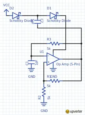
If I'm correct, when the opamp output goes high, the opamp is effectively shorting C2, which won't have the desired effect at all. Is there a way to reconfigure the circuit that will work?

MicroservicesOnDDD
  • 2,557
  • 1
  • 13
  • 48
Nick Johnson
  • 7,739
  • 3
  • 28
  • 44
  • Could you post a schematic of the constant current circuit you're working on as well, please? – MattyZ Feb 13 '13 at 16:07
  • 1
    What is your desired FET current. 1A/10A/100A - affects solution greatly. Use a MOSFET with lower Vgsth. Many exist. From memory the CES2310 and family (available in Asia, selectively elsewhere) would work well here. Also a number at Digikey. – Russell McMahon Feb 13 '13 at 21:48

2 Answers2

5

As shown you have a perpetuum mobile, none of which work. You are using the opamp as the energy source for itself and that dog won't hunt.

You can do what you want if you use external switches driven by the opamp - 2 x bipolar transistors or MOSFETS. The opamp then supplies only the drive energy to turn the "switches" on and off.

Lots of ideas here but

An opamp version of the circuit below would do what you want. The opamp (here = 555) can be powered from the output - initially its Vdd is two diode drops below Vcc_in but this rises as the circuit bootstraps its own supply.

Circuit from here

enter image description here


An alternative is to build a simple boost converter - oscillator (opamp or whatever) inductor, jellybean BJT transistor, a few resistors, diode, caps.Zener clamp output to regulate. Choose inductor size, frequency to suit desired power level.

Various examples here

including circuit below from here - good design notes on that page.

enter image description here

Russell McMahon
  • 147,325
  • 18
  • 210
  • 386
  • Thanks! Given the extremely low currents needed, is there any reason to build the switching regulator over the capacitative boost circuit? And won't the switching regulator be harder to bootstrap? – Nick Johnson Feb 13 '13 at 10:54
  • 1
    The boost converter bootstraps seamlessly and will supply an arbitrarily high Vout. eg 3V in 12V out or whatever. The capacitor doubler supplies 2 x Vin - 2x Vdiode_drop - 2 x Switch voltage drop. For Schottky diodes and eg 3v in Vout max is maybe 2 x 3 - 2 x 0.3 x 2 x 0.1 = 5.2V. This will vary with load etc. The boost converter is very easy - the inductor is the main issue but is very available. Inductance and frequency and duty cycle have to be right to avoid inductor saturation and power out depends on these too so it takes somewhat more design effort but is a very flexible solution. – Russell McMahon Feb 13 '13 at 21:57
1

The short answer is, no you can't.

The slightly longer answer is the reason you can't : a voltage doubler will indeed double the drive voltage (minus diode losses) but it is a far from ideal voltage source; it has a high output impedance (and one that is deceptively difficult to analyze - I can't find the recent question on that at the moment) but far too high impedance to drive the amplifier powering it.

EDIT : It can probably provide the "supply current" for the opamp itself; but that current doesn't include any current provided by the opamp's output into R1, R3 and especially C2. Include these and the actual supply current is far higher. END EDIT

If you need more voltage than a single stage of doubling can provide, you can add further capacitor/diode pairs fed from the same opamp, to build a voltage multiplier. I used a CMOS 555 timer to generate 60V from a regulated 12V supply. Unlike the circuit in Russel's answer, I omitted the transistor stage, feeding the capacitors directly from the 555 output.

  • The MCP6002 has a supply current of 100 microamps. Is the voltage doubler really that weak that it can't power that and a FET? – Nick Johnson Feb 13 '13 at 11:30
  • To clarify, are you saying that I can't do it using the circuit I provided, or I can't do it at all? If the former, then Russell's first circuit should work fine, correct? – Nick Johnson Feb 13 '13 at 11:55
  • If (say) the opamp drove a FET to power C2 etc - and the FET was powered from the original VCC supply - that would work, but then why run the opamp off a higher supply? Russell's circuit will work if the 555 is happy on 3V ; check its datasheet! –  Feb 13 '13 at 12:02
  • @NickJohnson - you have missed my perpetuum mobile" point. The doubler is being powered by the opamp output stage AND must power the output that is driving it. You are trying to get more out from the opamp than it gets from its own power supply - its own supply + FET drive + losses = perpetual motion. || External switches mean the opamp now does NOT supply its own power supply energy. – Russell McMahon Feb 13 '13 at 21:51
  • @BrianDrummond You must run the opmap off the HV output as th aim is to get a higher opamp supply voltage to supply igher MOSFET gate drive voltage. The 555 ccy was an example - I am suggesting he use the opamp as the driver in place of the 555. – Russell McMahon Feb 13 '13 at 21:52
  • @BrianDrummond - where the circuit is powering itself the external switches MUST be used. Otherwise the circuit supplies the output power via the opamp output plus supplies the load + supplies losses and must be an "overunity" device to work. – Russell McMahon Feb 13 '13 at 21:59
  • @RussellMcMahon I don't think I missed the point; I recognized it. My original thinking was that it would draw power from VCC via the first diode, but I realised after reading your post that of course that won't happen once the rail rises above VCC. – Nick Johnson Feb 14 '13 at 12:07