7

I am looking to construct a simple data logger to record the peak intensity from a flash strobe. When a flash is detected, the peak will be captured (ADC), time stamped and written to memory. The frequency at which these bursts of light arrive would be roughly 0.2 Hz (one every 5 seconds or so).

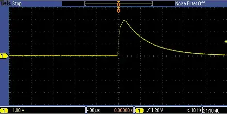
A typical output from my sensor in the presence of a flash strobe is shown below. The flash intensity is so great with respect to ambient conditions that detecting the flash is not an issue. In fact, I am already doing this to count the number of flashes.

Flash Output From Sensor

My problem then becomes sampling the peak value. My instincts tell me to utilize a sample and hold IC (LF398 for example). Looking at the datasheet, it seems I can achieve sub 10us acquisition times and that is acceptable to me. If I could then detect the peak (second derivative), I would know precisely when to hold. Problem is... I don't know where to start with that.

Am I going about this wrong? Any suggestions?

Jason
  • 1,923
  • 1
  • 20
  • 31
  • Page 9 of the LF398 datasheet http://www.ti.com/lit/ds/symlink/lf198-n.pdf has an example that sounds almost exactly like you need - edit worth a look but upon further thought you wouldn't know when to trigger it – PeterJ Feb 13 '13 at 05:24
  • 2
    It took some searching but I found an old question I once answered with a diagram of a peak detector and comparator circuit, that should be adaptable to your problem: http://electronics.stackexchange.com/questions/39357/peak-detector-peak-event/39376#39376 – The Photon Feb 13 '13 at 05:54
  • I agree with 'The Photon' - a peak detector circuit (or peak hold) will do what you want well. Look for rising edge. Wait 200 uS. Read value. Reset peak hold. Start again. – Russell McMahon Feb 13 '13 at 07:45
  • For interest, what detector are you using to measure the waveform with? – Russell McMahon Feb 13 '13 at 07:45
  • @RussellMcMahon The sensor is [here](http://www.digikey.com/product-detail/en/TEMT6000X01/751-1055-1-ND/1681410). I didn't have much choice in the sensor for reasons I won't get into but it actually seems like a reasonable choice for my application. Thoughts? – Jason Feb 13 '13 at 09:23
  • I'd say you were lucky - or perhaps the person who chose it did so by trial and error until they got a sensor that worked. | I say that because there is no respsonse data that I can see in the data sheet. It COULD have been far far too slow for your application. Evidently it's not :-) – Russell McMahon Feb 13 '13 at 10:20
  • @RussellMcMahon I am going to guess that it was chosen because of it's 'human eye responsivity'. – Jason Feb 13 '13 at 15:04

3 Answers3

4

A peak detector is something of a sample and hold that samples all the time, and holds the peak:

peak detector

Follow the input with this, and connect the output to your ADC. Make C significantly larger than the capacitance used by your ADC's sample and hold, or follow it with a buffer, so the voltage across C doesn't sag as you read it.

Trigger an ADC reading just after the event happens, and when it's done, close the switch to reset the peak, or make the switch a resistor forming an RC time constant significantly longer than the time it takes to measure the peak but significantly shorter than the interval between peaks to accept a little error but avoid the need to reset the peak detector.

Phil Frost
  • 56,804
  • 17
  • 141
  • 262
  • I'll go this route and see how it works. I think I'll use a GPIO tied to a MOSFET to discharge the cap and buffer Vout since I'll have two op amps in my package. – Jason Feb 13 '13 at 15:19
  • Give some thought to what happens when you close the switch: the op-amp's output is almost shorted to ground. Read the datasheet: your op-amp might not mind. If you have more questions on implementing the peak detector, that's probably best as a new question rather than a long discussion in the comments here. – Phil Frost Feb 13 '13 at 17:08
  • True... but a series resistor tied to the MOSFET should solve that. Thank you! – Jason Feb 13 '13 at 17:20
3

This looks like a solution for a T&H (Track and hold) circuit, like that from a TI (Burr-Brown) SHC605. There are many expensive solutions including those from from Analog devices that can do everything you probably need as well.

An alternative is a peak detector circuit or precision rectifier - with reset of course!

placeholder
  • 29,982
  • 10
  • 63
  • 110
  • This is very much like the electronics for beam position monitors used at high energy particle accelerators such as SLAC. – DarenW Feb 13 '13 at 05:49
2

I agree that the idea from @rawbrawb that a peak detector is the right approach for this project. Use a comparator to detect the leading edge of the flash pulse and then do a fixed delay, an R/C delay would probably work well, feeding into a second comparator. The output of that 2nd comparator would trigger your S/H and start the A/D conversion. The R/C delay would be long enough so that the peak detector has settled from the pulse capture. After your MCU has grabbed the A/D conversion the software could pulse an output GPIO pin that coupled back into the peak detector circuit and reset it back to minimum level and get it ready for the next peak capture.

There are numerous examples of peak detector circuits around that you can find in various vendor data sheets and application notes. The simplest of course is to feed the signal level through a Schottky diode and into a small capacitor. This of course has the disadvantage is that you lose some signal level equivalent to the forward bias drop across the diode.

Michael Karas
  • 56,889
  • 3
  • 70
  • 138