3

The phy chip I'm using has a evaluation board which grounds the chassis, connector and signal gnd points in the following way:

phy grounding

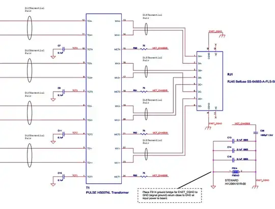
However, I don't really understand why the MCTx connections are connected through a resistor and cap to GND. I understand the ground bit - they are grounded to bias the center of the transformer, but don't understand the R and C between the MCTx and ENET_GND - if the unit (or cable plugged into the phy) is struck by lightning, then how is the R and C going to protect the rest of the circuitry?

With regards to the isolation between signal gnd and ethernet gnd (C13, 14, 16 and FB14) I came across this thread (Should chassis ground be attached to digital ground?) and am not too sure if it applies here (are chassis and ethernet ground the same thing?)

Is isolating signal and ethernet gnd in the manner shown above is good practise?, and if it is, what determines the values of the components to be used? Is it necessary for isolation between ethernet gnd and signal gnd to also be lightning proof?

stanri
  • 5,352
  • 2
  • 27
  • 54
  • I believe that is a fairly standard way for grounding Ethernet, if MCT stands for "Center Tap". Exactly *why* it is frequently repeated, I'm not 100% sure, which is why this isn't an answer but merely a comment. Take a look at this Mag-Jack datasheet, which integrates all magnetics and grounding into one housing: http://belfuse.com/pdfs/0810-2H4R-BG-F.pdf – dext0rb Feb 12 '13 at 06:43
  • The center tap is on the side of the transformer connected to the PHY, not on the line side. The line is completely floating with respect to chassis ground. – pjc50 Jul 13 '13 at 06:53

2 Answers2

2

It is typical for the Ethernet Center Taps to be connected through a 75 ohm resistor (one per center tap) and then all of them connected through a 0.01 to 0.1 uF 2-4KV cap to chassis gnd. I am not 100% sure, but it might even be part of the Ethernet spec to do it that way.

The other caps and bead between chassis GND and signal GND is done that way more out of ignorance or CYA than anything else "real". It is common to see people put those components in the schematics and then figure out how to best populate them during EMI testing. But, simply put, these components are not there because of Ethernet.

0

I don't think you can have lightning-proof ethernet. You can shield the equipment instead of trying to tame the kV's from inside.

My experience in grounding ethernet connectors is to make a local ground in the connector area and link it in a single point to the system (digital) ground. That grounding looks funny.

Joan
  • 1,403
  • 1
  • 9
  • 11