0

I remember the BJT transistor circuits are designed to compensate for the fact that the parameters of the transistor change with the temperature. I could not find similar ready-to-use solutions for the IGBT. My circuit should work in the switch mode (on/off). The input signal will be applied to the gate. Here its DC model (and the transformer for illustration): DC Equivalent Circuit
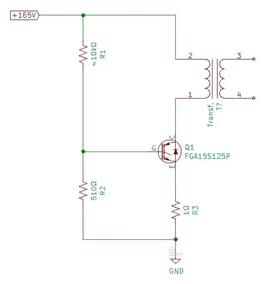
I know I have to adjust R1 to bias the gate voltage so the IGBT reacts to a small signal. Here's what gives me the pause. The specs for the transistor indicate that the bias voltage should be about +6.5 V at room temperature, but this voltage is too much for higher temperatures: Transfer Curve
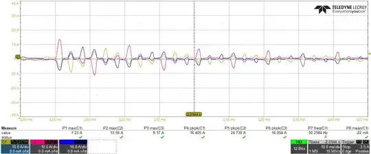
In fact the relation is such that I will have a thermal runaway: the greater the temperature, the greater the average collector current which in turn increases the temperature, and so on. I expect the collector current to be quite high: 10 A or more (peak value). What is the easiest solution to compensate for the temperature drift of the transistor?

I am not sure what the purpose of R3 is; it is a leftover from the original design. Maybe I can get what I need by adding a capacitor in parallel to it?

Here's the datasheet for the particular IGBT I am using: Datasheet PDF.

Thank you so much in advance.

SlowBot
  • 191
  • 1
  • 6
  • 1
    It's an IGBT, not an IBGT. – Hearth Jul 26 '21 at 17:43
  • 3
    *BJT transistor circuits are designed to compensate for the fact that the parameters of the transistor change with the temperature* Sure but actually **very few circuits** need that and use that. So **don't** fall into the trap which many inexperienced designers fall into and try to temperature compensate when it is actually not needed. First **prove** that you need it! For a switching application (transistor is either on or off) it is generally not needed. – Bimpelrekkie Jul 26 '21 at 17:46
  • 2
    The circuit you posted operates the IGBT in analog mode but you said you wanted "switch mode". If you're going to do switching (hard on/off), you don't have to care about the IGBT's transfer characteristics. What exactly do you want to achieve? What is this circuit for? – Jonathan S. Jul 26 '21 at 18:15
  • Why would you have thermal runaway just because you have negative temperature coefficient? – winny Jul 26 '21 at 18:56
  • don't design around transistor gain, you'll always be dissapointed. – dandavis Jul 26 '21 at 22:58
  • Are you wanting to run the IGBT in analog mode ? this is no mean feat if you do . – Autistic Jul 27 '21 at 09:46
  • @JonathanS., I do want the switching mode (complete on or off). However, I suspect my signal's amplitude at the gate is not enough to put the transistor in ON mode. Therefore I think maybe positive voltage bias, close to the where the "paddle" of the "hockey stick" meets its handle, will help. The transistor is a part of a ~20-40 kHz DC-to-AC convertor (or generator). The positive feedback signal is provided from the output transformer back to the transistor's gate. The original design employed a pair of BJTs; being a novice with the IGBTs I didn't realize they need > 10 V to switch. – SlowBot Jul 28 '21 at 02:24
  • Thank you, @Bimpelrekkie. My knowledge being quite rusty, your information really helps. – SlowBot Jul 28 '21 at 02:31

0 Answers0