9

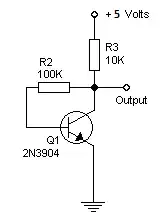
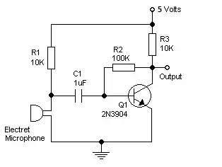
I'm looking to simply read the generic sound level from an Electret Microphone. I've seen a number of schematics with NPN transistors, that will provide an inverted output (~5V when quiet, ~0V when loud, linear operation in between).

Here's an example:

Simple Audio Preamp

However, I would like non-inverted output (linear operation, super quiet input gives ~0V, super loud input gives ~5V). I realize I could easily correct for this in software, but it just seems backward to me in a way and I cannot find any examples of a non-inverting output with a PNP transistor.

Is there a reason for this beyond being uncommon? If it's possible, could anyone provide a schematic of an electret microphone and PNP transistor that will give ~0V when quiet and ~5V when loud?

Further, is there some reason why this is so uncommon, or undesirable? NPNs seem to be used much more often than PNPs, why is this?

Edit

It seems I was rather confused in what I would get as output from the NPN preamp, which would be 0V for silence, and +/- Vin / 2. Here's what I want instead:

0V when silent, ~2.5V in medium sound levels, ~5V in maximum sound levels. This could be read by the ADC easily into 'sound level' without much work at all. However, I cannot feed voltages < 0V or > 5V to the analog comparator. It looks like I want the above with an envelope detector, however that would only get me from 0V to 2.5V. How do I make it vary the full 0V to 5V, 0V being 'quiet' and 5V being 'loud', with everything in between linear?

Ehryk
  • 1,141
  • 5
  • 16
  • 28
  • Unfortunately, this circuit will not generate a DC voltage, if the output is taken on the right side of C2. It will generate an AC voltage. This is because of the capacitors. Capacitors do not allow DC voltages pass through them. – abdullah kahraman Feb 11 '13 at 12:15
  • The Arduino has 6 analog inputs, which read 0-1023 for 0V-5V. AC is what I'd be looking for there, right? Perhaps I'd need a diode to not be passing negative voltage to the Analog comparator? – Ehryk Feb 11 '13 at 12:20
  • Yes, but a diode will drop 0.6V on itself. Maybe you should try to make the supply voltage 5V. The supply voltage is the one labeled "+3 to 9 Volts". Then remove C2. Then, read the analog value on the collector of Q1. Experiment with different sound levels, for example clap, talk, shout, be quiet, whisper, and see the analog reading changing. However, it will be a sine wave added with a DC value. – abdullah kahraman Feb 11 '13 at 12:24
  • Reading your question and comments it appears that your questiojn is not clearly stating what you want. It seems that you want an AC level which diminishes in magnitude as the input voltage increases. If this is the case you need to state it clearly. If this is not the case, can you please explain "I'm not looking for a logic 0-1, the Arduino's analog inputs have a 10-bit ADC that gives 0-1023 for 0V-5V, respectively" in this context. || ... – Russell McMahon Feb 11 '13 at 13:06
  • ... IF you are talking about DC levels the question is still unclear. An AC signal will be centred on the DC bias point. This is relatively fixed with signal strength. Can you very clearly and in simple terms explain EXACTLY what you want the output to do as the input signmal goes from 0VAC to Max Vin AC. – Russell McMahon Feb 11 '13 at 13:07
  • NPN transistors are used more commonly for these kinds of circuits probably in part due to tradition (in the 60's, NPN transistors matured sooner than PNP), and in part because \$V_{BE}\$ and the input voltage are nicely referenced to ground. PNP circuits are used when the load must be tied to ground. PNP transistors are used for amplifier inputs sometimes. For example, some op-amps have PNP inputs. – Kaz Feb 11 '13 at 14:03
  • The input is an analog pin that will register 0 at 0V, 1023 at 5V, and linearly in between (511 at 2.5V, etc). It seems an NPN in the above configuration would give me a linear AC signal, ~5V being quiet, approaching ~0V as it gets loud. I want the opposite: ~0V when quiet, ~5V when loud, and linear behavior in between. – Ehryk Feb 11 '13 at 14:07
  • As evidenced by the long comment chains and acknowledged by your edit, this question has unearthed some more underlying issues. Don't be afraid to close this question and ask new questions that specifically target the fundamentals you don't understand. This will lead to a more focused and useful response than trying to cover it all in this question. – Phil Frost Feb 11 '13 at 16:23
  • @Ehryk - I've just looked at your question and it seems you have approved Abdullah's answer as the "accepted" answer. Unfortunately the circuit and modification with the diode that abdullah has given you won't work as you expect. The output will be biased at half voltage and you won't get 0VDC for soft sounds and 5Vdc for loud sounds. I think you could re-open it (somehow) and next time be a little patient about accepting an answer until you are sure it is what you want. There are answers to this question that work ok. – Andy aka Apr 07 '13 at 15:24
  • @Andyaka I did not say anything that it will give what he wants, I just modified the circuit a little, explained it and told him to do the processing the signal digitally. Check my comments on my answer below. Also, I have written another answer [here](http://electronics.stackexchange.com/a/58703/5035) on his problem which shows an analog approach.. – abdullah kahraman Apr 07 '13 at 19:07
  • @abdullahkahraman I'm not wishing to disrespect you although in retrospect it may seem like my words seem this way. I saw that he had accepted the circuit but i felt it wouldn't work as he expected and didn't want him to think he'd been let down by this site. Sorry for any slur that you might have felt I had given. None intended. – Andy aka Apr 07 '13 at 20:18
  • @Andyaka lol, no offense taken :) I am trying to tell you the exact same thing. Since his question was not well put, it was hard to answer, however, I think he is satisfied after the other question and answers to it. – abdullah kahraman Apr 08 '13 at 16:06

4 Answers4

9

As far as I understood, you are trying to make some kind of a sound level detector, which will let you detect if there is a sound with a certain volume or not. You can do this with minor changes to the schematic you have. But before that, you should understand the circuit.

Let's break that circuit down. First of all the part with the microphone.

enter image description here

R1 is for supplying power that is needed by the microphone and this is called biasing the microphone. A microphone generates an AC voltage, which is sometimes negative and sometimes positive and it changes most of the time. Think of a sine wave. But remember, we had some biasing to it which is a DC voltage. We have to take that out and give only the AC voltage to the amplifier. And doing this is easy with a simple, single capacitor. A capacitor does not let the DC to pass, but lets AC pass easily. We have blocked the DC portion of the voltage on the electret microphone.

Now, let's look at the amplifier itself. Imagine that there is nothing else but the below schematic:

enter image description here

In this configuration, the transistor is biased to be in the linear region. It is in the edge of being turned ON or turned OFF, but it is neither of it. If it was fully ON, it would be saturated. If it was fully OFF, it would be not conducting at all. But it is in the middle, which is called the linear region.

When it is configured like that, if you touch (not literally) to the base of it, creating a small change, the output will be changing largely. This is what amplification called. You can beg Google for more detailed information.

What if we combine the two circuits mentioned above. A biased electret microphone with a capacitor will output small changes with respect to sound. The transistor will amplify these small changes so they can be viewed easily:

enter image description here

Notice that I have changed C1 to 1uF. You can use values up to 100uF. You will probably need electrolytic capacitors. Also, notice that there is no more an output capacitor. This means that you will have an output voltage somewhere between 0 and 5 V, depending on the sound level. If you have an oscilloscope, view the waveform on the output. If you do not, try lighting an LED if the analog read is higher than, for example, 750. Experiment with different values than 750, then report me the results.

abdullah kahraman
  • 5,930
  • 7
  • 59
  • 104
  • I understand most of that, thank you. Now because it is using an NPN transistor, the output will be about ~5V when quiet/input amplitude is low, and ~0V when loud/input amplitude high. This seems backward. Is there a way to modify it so that it behaves exactly as above, in the linear region, with ~0V meaning 'quiet' and ~5V meaning 'loud'? – Ehryk Feb 11 '13 at 14:12
  • @Ehryk Nope, the output will be somewhere between 0 and 5V. If you take a car siren and put it near the electret microphone, it will be a sine wave from with a peak to peak amplitude of 5Vpp with a frequency of about 300Hz. 5Vpp means it will go to 5V and come back to 0V with a sinusoidal shape. Have a look at [this](http://i.imgur.com/3IB13SV.gif). When there is a whisper, the peak to peak amplitude will be about 1Vpp with changing frequency because of the speech. That means it will go to 1V and come back to 0V. – abdullah kahraman Feb 11 '13 at 14:22
  • However, my comment above ignores the DC offset. – abdullah kahraman Feb 11 '13 at 14:25
  • Is there a way I can make it ~0V for quiet, ~5V for loud? Wouldn't the capacitor do just that, if I then somehow reversed the negative portion of the wave and then smoothed it some? With perhaps a bridge rectifier / diode bridge? (http://en.wikipedia.org/wiki/Diode_bridge) – Ehryk Feb 11 '13 at 14:28
  • @Ehryk Yes, you can add an output capacitor and an envelope detector. With the right component values, you will be able to have an analog voltage level depending on the sound amplitude. However, I am not sure of this. You should experiment. After getting results, just make an if-else condition in the software depending on the ADC value that you read. – abdullah kahraman Feb 11 '13 at 14:36
  • What would the circuit diagram look like? (I'm putting it on PCBs now, I can select and play with component values later). Could I get it to vary from 0V to 5V, or would I only be able to get 0V to 2.5V? – Ehryk Feb 11 '13 at 14:41
  • @Ehryk remove the output capacitor and add [this](http://i.imgur.com/N6UrFaU.gif) to the output. – abdullah kahraman Feb 11 '13 at 14:45
  • Wouldn't I need the output capacitor to bias it back to 0V? Otherwise the envelope detector would be 2.5V - 5V, right? I want to use the full range of my ADC. – Ehryk Feb 11 '13 at 14:49
  • Nope, think of it this way; add AC on to DC bias. Let's say DC bias is 2.5V. Adding AC of 4Vpp will make it go from 0.5V to 4.5V. Simple; (2.5V-2V) to (2.5V+2V). – abdullah kahraman Feb 11 '13 at 14:59
  • I still don't think that's what I want. I'm trying to get readings of 0 (0V) for silence, 1023 (+5V) for really loud things, 511 (+2.5V) for medium sounds, and then constantly sample it when I want to know how loud it is. How can I do this? – Ehryk Feb 11 '13 at 15:05
  • I'm guessing that's 10Vpp on a DC bias of 0V, passed through an envelope detector. How is that accomplished with 5V? – Ehryk Feb 11 '13 at 15:07
  • @Ehryk please edit your question so that you are more understood. Maybe others can help you with this. Remove the parts with PNP and polarity. Mention that you want 5V output for the highest sound level, 0V for the lowest level and 2.5V for the medium sound level. So that means you want an analog voltage output with respect to sound level. State this in your question clearly and in detail. – abdullah kahraman Feb 11 '13 at 15:34
3

The common emitter class A amplifier is always inverting even if you use a PNP, the only difference is you invert the power supply polarity. If you use an audio transformer instead of a capacitor you could change the signal phase as you please. But it will probably cost more than use two BJT. In order to solve your final question anyway, you have to rectify ( even with a single diode ) the output and apply the result to a load ( a resistor would be fine ) and feed this to the arduino analog input. There is no reason to invert the signal at all.

Felice Pollano
  • 853
  • 9
  • 20
  • Then what is the simplest non-IC non-inverting amplifier (irrespective of class or common-emitter)? – Ehryk Feb 11 '13 at 12:21
  • The common collector, but I think is not correct to use in this case, since you need a voltage gain – Felice Pollano Feb 11 '13 at 12:23
  • The common-base, if you need voltage gain (but its current gain = 1). Note that you could add a second inversion in this instance by simply interchanging R1 and the microphone. No PNP necessary. However inverting or not will NOT solve the stated problem - generating a logic 1 or 0 depending on the loudness. –  Feb 11 '13 at 12:38
  • I'm not looking for a logic 0-1, the Arduino's analog inputs have a 10-bit ADC that gives 0-1023 for 0V-5V, respectively. Can you give circuit diagram for this? – Ehryk Feb 11 '13 at 12:50
1

This amplifier inverts the signal, but you shouldn't care for an audio signal. What you'll have at the output is AC, a capacitor blocks DC. So, you cannot say ~0V for quiet noise and ~5V for loud. If what you want is a sound level sensor, one easy way is to add, after the output cap a circuit called "demodulator" or "peak detector", easily implemented around a diode and a few passive components.

Joan
  • 1,403
  • 1
  • 9
  • 11
  • Can you add a diagram of this? Also, wouldn't the peak detector vary between -2.5V and 2.5V? I would want ~0V to be quiet, and ~5V to be the loudest, how would this be accomplished? – Ehryk Feb 12 '13 at 02:28
0

Simply invert the output a second time, using a 2 stage amplifier. (See this page for more info on two stage, and non-inverting transistor amplification. Very insightful)

enter image description here

The same value resistors and capacitors, the same 2n3094 transistor, added to the output of your existing schematic, would provide a second inversion.

But someone correct me if I am wrong, but your schematic shows a simple biased amplifier, so you would really have 2.5v as the quiet range, and the waveform gets larger with more sound? You will have a ±2.5v peak to peak. You would have 1v/3v as a middle loudness.

Passerby
  • 72,580
  • 7
  • 90
  • 202