4

In a building infrastructure there is coaxial cables for TV. The first end of all the cables is on the roof. The second end for each cable is in different apartment.

The problem is that I don't know which cable is connected to which apartment. So I thought that doing short circuit test might do the job. But:

  1. The cables lengths are [20m-50m]
  2. I can't get the two ends near each other (DUH!)
Yousf
  • 159
  • 1
  • 1
  • 5
  • 3
    Perhaps short the cable core and shield together at one apartment at a time (you can make and carry a simple coax female connector with a short between its terminals), then test the continuity between core and shield at the distribution end? That's a short-circuit test that does not need bringing the cable ends near each other. – Anindo Ghosh Feb 11 '13 at 11:00
  • @AnindoGhosh will this work with normal 5-volt multimeter? – Yousf Feb 11 '13 at 11:10
  • It might be good to try it, I assume you have 50 meters of cable accessible. It would be a non-destructive test, so easy to check, I propose? – Anindo Ghosh Feb 11 '13 at 11:16
  • 2
    Extend Anindo's answer. Measure the resistance of 50m of coax with the far end shorted - let's say it's 10 ohms. Make 4 of his connectors; one shorted, one each with 20, 40 and 60 ohms. Visit 4 apartments putting one test connector on each cable. On the roof you should have no difficulty identifying each tester - saving you a lot of stairs! –  Feb 11 '13 at 12:13
  • @BrianDrummond why such low resistor values? Why not pick kilo ohms? That would easily take the DC resistance out of the equation. – jippie Feb 12 '13 at 19:15

2 Answers2

2

Writing up my comment as an answer, incorporating Brian Drummond's excellent improvement upon the concept.

  • Take an unused 50 meter length of coaxial cable, or somewhat more or less, depending on what you have handy. Even if it is still in a roll, that will work if you can reach both ends of the cable.
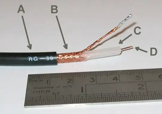
  • Strip a few inches off each end of the cable, pull the shielding braid to one side and twist it, and if you want to be a perfectionist, use some soldering flux and solder the twisted braid end. The result should look like this:
    Coaxial Cable End From Wikipedia
  • At one end, solder the shielding braid to the central core wire - or just twist them together for a firm connection.
  • At the other end, apply your normal 5-Volt multimeter in resistance measurement mode between the braid and the core wire. The resistance you read will give you an estimate of how much resistance the typical cables in use should have, shield-to-core, for a given length.
  • Let's say that number is 10 ohms for 50 meters (per Brian Drummond's example).
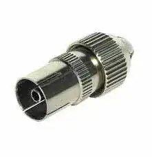
  • Now, take a few coaxial female connectors like this one:
    Coaxial Connector
  • On the first, use a bit of copper wire to short-circuit the shield tab and the central core tab, at the back of (or inside) the connector's metal housing. That's your zero-ohm connector.
  • On the second connector, use a 47-Ohm resistor instead of the copper wire, same process: connect the core tab to shield tab using the resistor.
  • For the next few connectors depending on how many houses you have to identify cables for, use 100 Ohms, 150 Ohms, 220 Ohms, 270 Ohms, 330 Ohms, and so on (standard resistor values about 50 Ohms apart each).
  • Visit each house, take their cable off the set top box or TV, and plug it into one of the connectors you've modified above. Keep a note of which resistance went to which house.
  • Back on the roof, measure the resistance between central core wire and shielding, for each of the cables, using your multimeter.
  • The cable with the least resistance (say anywhere from 5-20 Ohms) will correspond to the zero-Ohm connector. Cable indicating 47+x Ohms (say 55 to 70 Ohms) has the second connector, 110 to 120 Ohms has the third connector, and so on.
  • With the suggested resistor values, you won't really have to worry about different cable lengths, because the margins are big enough to allow for a 5 to 30 Ohm difference in cable resistance, which should suffice for a wide range of cable lengths.

Summary:

In one measurement session, you will have identified the cables belonging to all the houses, from the roof distribution unit. You can thank Brain Drummond for the walking and stair-climbing effort you saved.

Anindo Ghosh
  • 50,188
  • 8
  • 103
  • 200
  • I think you can skip steps 1-5 if you use resistors like 1k, 2k2, 3k3, 4k7. If the cable is so poor that its own impedance is anywhere near 5k for 50m and thus infuencing the measurement, then it should be replaced anyway. – jippie Feb 12 '13 at 19:20
  • It's worth pointing out that my suggestion is problematic if the coax terminations in any of these apartments have TV sets plugged in! I should have mentioned this too. Jippie's point about higher impedances is also good, as long as there isn't much stray radiation current to mess up the readings. –  Feb 12 '13 at 19:50
  • 1
    @BrianDrummond That's why my steps include "*Visit each house, **take their cable off the set top box or TV**, and ...*" – Anindo Ghosh Feb 13 '13 at 02:35
1

1st - I suppose you cannot visually track every cable, they are inside the walls.

2nd - I suppose every coax go to a separate antenna.

So, the simplest test I can imagine is this. It requires some collaboration but zero equipement: disconnect all antennas but one. Check who has the best signal in these conditions. Repeat for (N-1) cables.

Joan
  • 1,403
  • 1
  • 9
  • 11