1

This would be considered a basic electronics question that I should know (I've been all over the place with questions tonight and I apologize).

But anyways using this circuit (It's a TTL SR latch)

Simulation Link But the picture below shows the current flow in yellow. (This is the circuit linked above) enter image description here

Anyways I mostly understand the circuit, yellow is current flow. Makes SR latches make more sense......but how come current isn't flowing into "OUTPUT" where I pointed with my Red arrow. I mean the Compliment Output doesn't really have much different, I mean current is flowing right next to both......or is this because this is on conventional current? I guess I just don't understand why both outputs are not High regardless....since we have current flowing right next to them (The dot over wires on them means they are connected correct?)

To Put simply I guess also: Why does this show High enter image description here

But this shows Low enter image description here

When they are practically the same circuit....but one output is literally just lower than the other?

  • 4
    In your simulation, current can't flow to the output, because there's nothing connected to the output for current to flow into. – The Photon Feb 11 '13 at 06:50
  • I guess im confused at why Current can flow out of the Output Complement and not just the Normal Output, the difference is that Q2 has current coming from it's Base that goes into Output Complement, but Normal Output has Current flowing right next to it...so I don't see why it cannot be high either. –  Feb 11 '13 at 07:07
  • as another aside, this is an RTL SR latch (Resistor-Transistor Logic) not a TTL one, since you use resistors not transistors to pull up to 5V. TTL is a bit more complex, but usually faster and lower power. –  Feb 11 '13 at 10:59
  • @Sauron, There's no current flowing out of out-bar in your circuit either. The bright green color indicates voltage, not current. The yellow dots indicate current, and none of them are flowing out of either of the output terminals. – The Photon Feb 11 '13 at 16:58
  • @ThePhoton, makes sense....but why is there no current flowing out then? or just because it's not a complete loop..and if thats so then why is the upper Logic Out High? –  Feb 11 '13 at 17:13
  • There's no current flowing, because you haven't hooked up any wires or other devices for it to flow into. See Phil's answer, especially the first bullet point. In the water & pipes analogy, an open wire in electronics isn't like the open end of a hose, it's like a stoppered end of the hose. It allows high pressure (high voltage, by analogy) to build up. – The Photon Feb 11 '13 at 17:17

4 Answers4

2

I believe the secret is in the transistors. The current on the right half is flowing straight to ground because of Q2. Q2 is active because of the small current to its base, the vertical line, from the left side.

The next question is why Q1 doesn't get activated like Q2. What prevents this is the 1K resistors. Once the current is past the 100 resistor on the left side, the only place to go is into Q2's base. On the right side, because of the 1K resistor, most will just run to ground and Q1 is never tripped.

When you press the Set switch, Q1 is switched on by applying current to its base and the reverse happens. Current on the right is now diverted to keeping Q1 open and current on the left runs straight to ground.

Swanand
  • 3,245
  • 5
  • 28
  • 45
Pat S
  • 21
  • 1
  • I think this makes some sense, Since the current is flowing straight to ground since Q2.....it's not going to divert. I guess I have it in my head that electrons are going everywhere....but they want to go to ground. –  Feb 11 '13 at 07:26
2

The answer is fairly simple:

The Falstad Electrical simulator has non-realistic components.

Basically, the "Output" components are "perfect" voltage measuring devices, that can measure the voltage at a node while drawing no current. As such, since they draw no current, there is no current flow into or out of them.

Circuit description is as follows:

  • Anyways, the way the circuit works is that when one side (lets say Q1) is turned on, it pulls the voltage at it's collector down to below 0.6V.
  • Since the collector is at such a low voltage, no current can flow though the 1K resistor connected from Q1's collector to Q2's base.
  • Since Q2's base is being held below 0.6V by Q1, no current can flow from the collector to the emitter of Q2.
  • Therefore, the voltage at Q2's collector rises until the current flow through the 1K resistor to Q1's base reaches equilibrium.
  • Finally, since we have current flowing into Q1's base, the system state stays stable.

If this isn't what you're asking, please try to edit your question to be more clear. I'm not too sure what exactly you're trying to ask.

Connor Wolf
  • 31,938
  • 6
  • 77
  • 137
2

Firstly, understand that a complete circuit is required for current to flow[1]. Current does not flow from the power supply to ground. Rather, the power supply (let's say a battery) pumps current through it. Thus, you will always be able to draw a full loop of current flow. Most schematics don't draw the full loop to keep the diagram visually simpler, but if you make a flashlight with a battery and a lamp, you can clearly see how the loop is actually there.

Secondly, high and low are relative measurements of electromotive force, more commonly called just voltage because it's measured in volts. No current is necessary for a voltage to exist. Voltage is an electrical potential, like tension in a spring is a mechanical potential. Here are some rhetorical questions which might get you thinking in the right way:

  • If you block the end of a hose and open the spigot, how does the pressure change? How much water is flowing?
  • What has more potential energy, a rock at the top of a cliff, or an identical rock at the bottom of the cliff? Are they moving?
  • What happens when you push on a brick wall? Can the force be detected? Does the wall move?
  • How much current is flowing in a battery not connected to anything? What's its voltage?

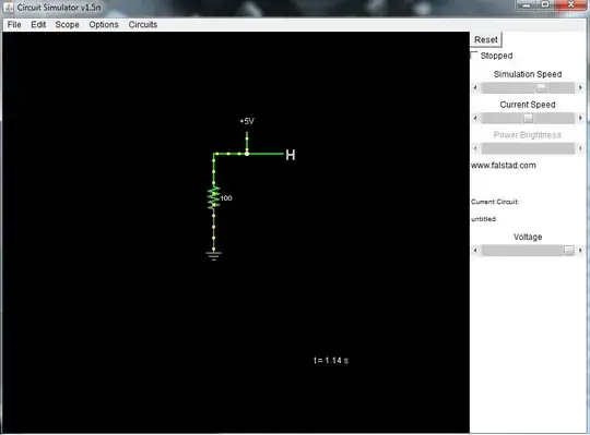
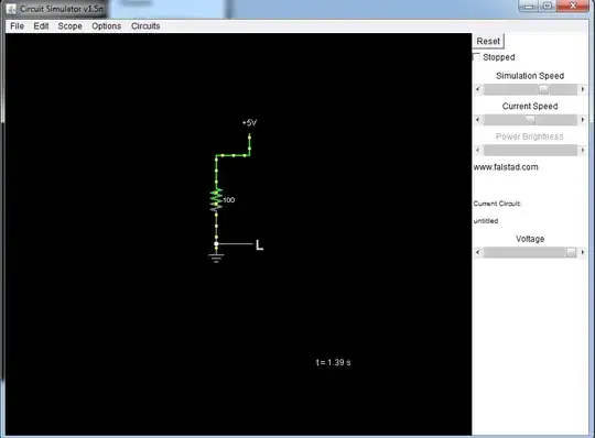
There are a couple approaches to understanding why one side of the resistor can be high, and the other can be low. First, go find a AA battery and some resistors of several values greater than \$470 \Omega\$. Measure the voltage across your battery. It should be about 1.5V. Now connect a resistor across the terminals (this is what you have in your schematic). Measure the battery voltage again. It should still be about 1.5V. In fact, it doesn't really matter at all what value the resistor is; the voltage will be the same.

The difference is that with a small resistor, a large current will flow, but with a large resistor, a small current will flow. As the resistance approaches infinity, the current approaches zero, and when the battery is not connected to anything at all, there is no current. The voltage in all cases remains the same. As the resistance approaches zero, the current approaches infinity, but you won't actually get that far, since that would imply infinite power, which is impossible. Instead, something will get hot, melt, or explode, unless your battery is dead before that happens.

A hydraulic analogy can be made with a centrifugal pump with its input and output connected with a hose with a variable restriction (resistance) in it. If the hose is entirely pinched shut, no water will flow, although there will be a difference in pressure on either side of the pinch. As the pinch is opened (resistance decreases) the pressure remains the same, but more water (current) flows.

At some point, the resistance provided by the pinch will be small compared to the friction inside the pump and the hose, and the pressure difference will decrease, and the pump will be pumping as much water as it can. This sort of condition is usually avoided in electrical design, since it will run down your battery or run up your electric bill very quickly while not doing much useful.

Ohm's law states this in mathematical form: voltage \$E\$ is the product of current \$I\$ and resistance \$R\$:

\$E = IR\$

We know the battery voltage (\$5V\$ in your schematic) and you are picking the resistor, so we can rearrange that equation algebraically to find the current for any resistor:

\$ I = 5V / R \$

[1] at least, until you get into RF circuits, which exploit the propagation of electric waves without a complete loop. See How does the current know how much to flow, before having seen the resistor?

Phil Frost
  • 56,804
  • 17
  • 141
  • 262
  • Ok this makes sense, then why is on my circuits (the bottom 2) High is on the top and low is on the bottom? The voltage should be "almost" identical. a 100ohm resistor can't change the potential THAT much right? and you are sayting that digital highs and lows are measured in current correct? –  Feb 11 '13 at 17:19
  • 1
    @Sauron no, _high_ and _low_ almost always indicate voltage, not current. [There are a few logic families that encode _true_ and _false_ with current](http://en.wikipedia.org/wiki/Emitter-coupled_logic) and not voltage, but they are rare. I'll edit my answer to address your other questions. – Phil Frost Feb 11 '13 at 17:30
  • Ok that makes sense...but Im still not sure I understand why in my schematic (last 2 images) one is high and one is low if the voltage is the same? –  Feb 13 '13 at 06:18
  • @Sauron the voltage isn't the same. That's what _high_ and _low_ are telling you. The voltage at each end of the resistor is the same as the voltage at the end of each end of the battery, because the wires connecting the resistor to the battery are a _much_ lower resistance path, and thus drop much less voltage (E = IR), than the resistor. – Phil Frost Feb 13 '13 at 11:12
  • Ok thats why Im confused. Overall the drop even at the end towards ground should be very small (since the wires resistance is almost neglible, and the resistor is very small). So it seems like it should still report a HIGH. –  Feb 13 '13 at 19:31
  • @Sauron maybe this discussion would be better served [in chat](http://chat.stackexchange.com/rooms/15/electrical-engineering). – Phil Frost Feb 13 '13 at 20:49
  • agreed! sorry just now saw this, ill try to find u on there soon! –  Feb 14 '13 at 00:32
1

I wrote a really verbose answer that goes back to basics, and I also wrote a summarised answer, just in case my initial answer was too simplistic.


Here's the summarised version:

In your second and third circuits:

  • The resistor is using up a large chunk of the potential energy in the circuit. Before the resistor (as in, on the +5V side), the potential energy is high (and so it's a high voltage)
  • After the resistor (GND end), the potential energy is low (and so it's a low voltage)
  • It's not that the output is literally lower, it's that the one output is closer to gnd than the other, in terms of potential.

The highlighted wires in that simulator aren't really showing current flow, they're rather showing areas of high potential (highlighted) and areas of lower potential (non-highlighted)

The operation of the first circuit has been pretty well covered by the other answers.


Here's the verbose version:

It's important to establish here the difference between current and voltage. Voltage is always measured between two points - it quantifies the difference in energy potential between those points. A voltage measured with no reference is meaningless. So if you take a battery and you probe either side of the battery with a multimeter on the (DC) volts setting, you will see 1.2V or 9V or whatever the batteries potential is.

Current is the amount of energy that is being transferred from the higher point to the lower point. If you throw a boulder off a cliff, it will fall at a different speed depending if it's falling through air or water or some kind of gas. The speed the boulder is falling is dependant on the resistance of the medium through which it moves. In the same way, current will flow from higher potential to lower potential wherever possible, and it will do so as fast as it can given the medium it's in.

So looking at your last two circuits,

  • There is a high point and a low point of potential (+5V and GND)
  • There is a connection between the two points (a wire), meaning that current can flow from the higher to the lower.
  • There is a resistance which is going to limit the flow of current between the high and low potential.
  • As far as I can see, the highlighted lines in the simulator are not current flow, but rather showing what parts of the wire are a high potential (highlighted) vs lop potential (non-highlighted).
  • Since the resistor is resisting the flow of current (and that's what it's designed to do), it's taking away a whole bunch (the vast majority in fact) of the energy in the circuit.
  • Before the resistor, there is a lot of potential energy (and so that part of the circuit is "high")
  • After the resistor, there is very little potential energy (and so that's why that part is "low")

Looking at the top circuit:

  • A transistor is a switch, essentially, which has high resistance when "off" and a low resistance when "on".
  • Q1 is on and Q2 is off.
  • Since Q2 is a very high resistance, the majority of current is going to flow through Q1 instead.
  • Notice the resistor values. 100 ohm is 1 tenth of 1000 ohm (1k), so 10 times the current is going to flow through a 100 ohm resister than a 1k resistor.
stanri
  • 5,352
  • 2
  • 27
  • 54
  • But would a 100ohm resistor really do that though? I mean that's so small? I don't see how it would impede it? –  Feb 11 '13 at 17:14