1

I'm making a 400V adjustable buck converter. I am controlling it with an ESP32. For some reason, if I set the PWM frequency to higher than just 200Hz and a bit rate of 4, the IRFB11N50A MOSFET doesn't close in time.

For example, when the chip is set to a duty cycle of 50%, there would run 375V through the MOSFET, and at 75% around 385 V, like the 0-100% only goes from 350 V to 400 V.

I'm guessing this is because the MOSFET doesn't close in time. (This is when the frequency is above 200 Hz, and the higher the worse it gets, at 100 kHz it's just on all the time.)

I'm not sure why it can't close faster than 200 Hz since the datasheet says its maximum frequency should be something around 8 MHz. What did I do wrong?

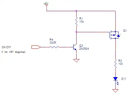
Wiring: enter image description here

(Sorry for the confusion, anciently added the wrong component)
Andrew Morton
  • 2,389
  • 1
  • 17
  • 26
  • 2
    Is that schematic correct? The body diode of Q2 is shorting the 400 V supply. – tim Jul 24 '21 at 14:14
  • Please fix the schematic. What are you driving with the MOSFET? – StarCat Jul 24 '21 at 14:21
  • I guess the schematic is a bit miss leading, ill make an edit explaining, – Marius Wanscher Jul 24 '21 at 14:30
  • 2
    Please give us the actual schematic instead of the wrong one plus text. – Marcus Müller Jul 24 '21 at 14:44
  • Putting 400V across a 1k feedback resistor, operating at such a low f as 200 Hz and a reversed Pch source pin and drawing ground upside down all explain why you are having difficulty. – Tony Stewart EE75 Jul 24 '21 at 14:57
  • could you maybe elaborate for the less educated? @TonyStewartEE75 – Marius Wanscher Jul 24 '21 at 14:59
  • Draw circuits with current flow from top to bottom. Higher voltages at the top, ground symbols pointing down towards the ground. See [rules-and-guidelines-for-drawing-good-schematics](https://electronics.stackexchange.com/questions/28251/rules-and-guidelines-for-drawing-good-schematics) if you're interested in learning more. It would have helped you spot the diode problem. – Transistor Jul 24 '21 at 14:59
  • what do you mean with the diode problem? @Transistor – Marius Wanscher Jul 24 '21 at 15:04
  • 3
    If you don't understand what the diode problem is, you should really reconsider working with 400V circuits. 200Hz isn't really a suitable switching frequency for a 400V buck converter, the inductor would be huge. There are safety issues like isolation and creepage and clearance that you need to understand before working on high voltage circuits. Work with someone who knows power conversion, or stick to low voltage circuits until you learn a lot more about power electronics. – John D Jul 24 '21 at 15:10
  • I know 200Hz is way too low, and I want it to be in at least above 200kHz, but the MOSFET is not closing faster than 200Hz, apparently, there is a problem with the diode, i have no idea what that means, and is why I'm asking, my safety is my own concert, would you maybe explain what the diode problem is? – Marius Wanscher Jul 24 '21 at 15:19
  • @MariusWanscher: You can't tell much about switching speeds using a multimeter. You need an oscilloscope to be able to **see** what is going on rather than guessing based on readings from a device that isn't made for what you are trying to make it do. – JRE Jul 24 '21 at 15:22
  • 1
    @MariusWanscher The gate threshold voltage for that MOSFET is 2–4 V, so at 3.3 V the ESP32 might not even switch it on. You could use a bipolar transistor to drive the MOSFET with a higher voltage - and that would be able to supply more current than the ESP32 to switch the MOSFET faster. Also, there's a chance the cheap transistor will blow up instead of the expensive ESP32 if something goes wrong. – Andrew Morton Jul 24 '21 at 15:51
  • yes, but since it works at low frequencies the 3.3v is enough, I tested with a second adjustable power supply, and at 2v it opens for around 200v and at 3v it is completely open, I should probably add some protection for the esp32 maybe just a diode, but what do you mean with higher switching speeds at higher currents? i thought MOSFETs were only about voltage? – Marius Wanscher Jul 24 '21 at 15:56
  • 1
    @Marius, I see from your comment to JRE that you've understood "the diode problem". I see also that you have modified the schematic. Now it is much more clear that current flows from top to bottom and the diode is reverse biased and will not conduct. Good work. – Transistor Jul 24 '21 at 15:59
  • thanks for the link was helpful i guess – Marius Wanscher Jul 24 '21 at 16:02
  • 3
    "i thought MOSFETs were only about voltage"- The gate is basically a capacitor. To switch quickly and get the voltage you need on the gate you have to charge that capacitor quickly. That takes a lot of current: I=C*dv/dt or dv/dt = I/C. So you need the ability to deliver large currents to the gate for a short time. A GPIO is not a good FET driver. Also, just because you think you see the FET switch on at 3V doesn't mean it will be fully on with the specified ON resistance. Look at the datasheet spec for the voltage you need to get the specified RDSon. – John D Jul 24 '21 at 16:38
  • @MariusWanscher The gate of the MOSFET is a capacitor, when it is discharged it presents the same short-circuit as any other capacitor. The ESP32 I/O can only supply a limited current, so it takes quite a long time to charge the gate capacitance, and while the MOSFET is not switched on completely it has more resistance. More resistance = more heat generated. Edit: John D put it better. – Andrew Morton Jul 24 '21 at 16:39
  • oh i see, thanks – Marius Wanscher Jul 24 '21 at 16:44
  • Is that the full schematic? Because that is _not_ a buck converter. – marcelm Jul 24 '21 at 17:11
  • @marcelm no ofc. not, this is just about using the MOSFET as a switch, and why it is closing slowly (probs too low current from esp32, ill try a bit later), I guess imagine a big coil, capacitor, and diode (: – Marius Wanscher Jul 24 '21 at 17:23
  • As drawn, the circuit shown by the schematic will still destroy the FET as soon as it manages to turn on. – John D Jul 24 '21 at 17:24
  • 1
    In that case, I'll repeat what @MarcusMüller said: Please give us the actual schematic instead of the wrong one plus text. – marcelm Jul 24 '21 at 17:26
  • I guess mentioning the use of the MOSFET is misleading to you, but as both answers and all other comments is on, this is not about making a buck converter, it's just about the MOSFET and turning it on and of, and why it arent closing fast enough. – Marius Wanscher Jul 24 '21 at 17:31
  • 1
    @MariusWanscher The first sentence of your question is "I'm making a 400V adjustable buck converter," which very much makes it read like it is about making a buck convertor ;) – Andrew Morton Jul 24 '21 at 19:22

2 Answers2

1

You've got at least a couple of problems here. I see two things wrong with your transistor circuit. On top of that there's your multimeter to consider.

To the MOSFET:

  1. The way your diagram has it connected, current will flow through the MOSFET body diode. This connects your 400VDC to ground through the diode that is part of all MOSFETs. The diode is shown in the schematic symbol. A diode conducts when the anode (flat side of the triangle) is at a higher voltage than the cathode (straight bar at the point of the triangle.)
  2. The 2N7002 is only rated for 60 volts from drain to source. If you put your transistor in the right way around, it'll just go "pop."

Your MOSFET probably isn't really "switching" much at all, given that it is hooked up backwards.

Finally, we get to the multimeter.

Typical multimeters can't deal with high frequencies. They can work with typical AC power line frequencies (50 or 60 hertz) and a bit more. They are unlikely to function properly at kilohertz frequencies. 100kHz is right out.

JRE
  • 67,678
  • 8
  • 104
  • 179
  • Sorry, I'm an idiot, didn't realize before now i added the wrong component in the schematic, i understand the confusion now, and what you meant with diode problem – Marius Wanscher Jul 24 '21 at 15:29
  • I missed it but your 400V buck has a 400V output what is the input? You need a gate driver, it needs to supply some current, the gate capacatance is quite high. Also 500V is cutting it close, with care it would work. – Gil Jul 24 '21 at 21:56
1

Another issue: capacitance. There is some effective capacitance associated with the multimeter and wiring. When you turn on the FET, the capacitance will be charged up very quickly, with a time constant of Rds(on) x C. When the FET turns off, the capacitance will be discharged through the multimeter, which has a very high (normally at least 1 M ohm), and will discharge much more slowly.

At high frequencies, the capacitor will have little opportunity to discharge, and the multimeter will show a high voltage.

For instance, let's say the multimeter (and wiring) have an effective capacitance of 100 pf. Then if the multimeter has an input resistance of 1 M, the time constant for discharging the capacitance will be 10 usec. A 100 KHz square wave only provide a discharge time of 5 usec per cycle.

WhatRoughBeast
  • 59,978
  • 2
  • 37
  • 97