2

I am controlling a BLDC motor (24V, 125W) with this IFX007T board controlled by an STM32L412 MCU. The PWM frequency should be around 40kHz (I have 80MHz clock, counter period of 512-1 and prescaler of 4-1). I am using the hall sensors and a commutation table. I use FreeRTOS and the BLDC task has realtime priority. On each phase I have an LC filter with 40uH and 680uF. I have removed the two 220nF (from phase to VCC and GND) capacitors on the board. The motor is turning (more or less quietly) but it is not as strong as I would expect it to be (I am using it to run a rotary vane pump, which it can't manage to do right now). The picture on the oscilloscope looks like this: bldc with filter If I remove the filter, I see this: bldc without filter
however, from what I understand, it should actually look something like this (source): expected oscilloscope image
Does anyone have an Idea why I don't see nice slopes between the steps? And why do I have a lot of peaks despite the filter?

UPDATE 1: This is what the PWM looks like: pwm in the "transition part" the PWM is set to half of the maximum duty cycle, but the phases are actually left open since the enable pin is pulled low on the IFX007T.
UPDATE 2: These are the hall sensors and one of the phases: hall sensors and one phase
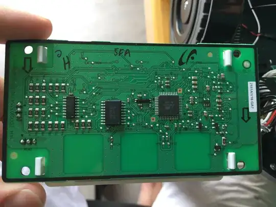
UPDATE 3: SOLUTION the commutation was wrong, once I adapted it using this table, the motor spins quietly and the waveform looks as expected!
lazerlini
  • 57
  • 6
  • Interesting. How does your PWM outputs from your controller look? – winny Jul 21 '21 at 16:26
  • @winny I added the PWM screenshot to the post. – lazerlini Jul 21 '21 at 16:49
  • how much current is it pulling? – Aaron Jul 21 '21 at 17:29
  • @Aaron for debugging I am running it at ~20% duty cycle. With no load attached it pulls around 1A, when I attach the pump, it won't start spinning and the current will go up to 7A. Even at 100% duty cycle it won't spin and the current will exceed the maximum rated current of the motor (also, my multimeter only goes up to 10A). – lazerlini Jul 21 '21 at 17:39
  • Thanks. That does the output stage schematic look like? – winny Jul 21 '21 at 18:33
  • @winny it is linked in the post above, I just used [this IFX007 arduino board](https://www.infineon.com/dgdl/Infineon-Motor_Control_Shield_with_IFX007T_for_Arduino-UserManual-v02_00-EN.pdf?fileId=5546d462694c98b401696d2026783556), the schematic is in the pdf. However I removed C14, C7, C5, C6, C2, C8 – lazerlini Jul 21 '21 at 19:24
  • _"On each phase I have an LC filter with 40uH and 680uF._ - Exactly where do you have these connected, and which specific components are you using? – Bruce Abbott Jul 21 '21 at 22:08
  • @BruceAbbott I just connected the output of the board to the [coil](https://www.mouser.ch/ProductDetail/80-SN20P-240) and the other end of the coil to the [capacitor](https://www.mouser.ch/ProductDetail/710-860010575015) to ground and to the motor (for each phase). – lazerlini Jul 22 '21 at 13:09
  • 1
    The drive waveform should look symmetrical (like your ”good” example of a BLDC motor without LC filter), yet the voltage in your motor is much lower during ramp-up than during ramp-down. I suspect that your drive waveform is actually leading the rotor by roughly 60 electrical degrees, which would explain why the motor runs like crap. – jms Jul 22 '21 at 14:25
  • @jms you are correct, it is also visible in the last image I uploaded. if you want, you can post your answer (not just as a comment) and I'll mark it as the solution, thanks a lot! – lazerlini Jul 22 '21 at 16:33

1 Answers1

1

The voltage should ramp up while the phase is floating due to back-EMF from the motor, then stay at a constant high value while that phase is driven high, then ramp down due to back-EMF while the phase is floating again, and finally stay low while the phase is driven low. Your ”good” example exhibits this behavior, your actual measurement doesn't:

enter image description here

As you can see, the waveform isn't symmetrical - the voltage is much lower during the floaty bit prior to a phase being driven high than the one after.

I suspect that your drive waveform is actually leading the rotor by roughly 60 electrical degrees, which would explain why the motor runs like crap

jms
  • 8,504
  • 3
  • 22
  • 45