I am trying to obtain the hysteresis curve of a iron core transformer.
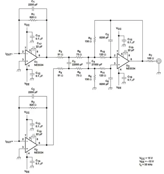
To integrate the voltage output from the secondary coil, I used an LM741 opamp, 10k ohm resistor, 0.1uF capacitor, and 1M resistor. This is my setup. Later, I actually added a capacitive voltage divider on another breadboard in addition to what is shown (this is mentioned later in the following text.)
 Initially, I got a largely saturated and almost distorted curve with 1V as the AC power supply. I then realized that 1V is too large.
The transformer's primary coil is 600 turns 2A, the secondary has 300 turns 4A. The input voltage into the opamp integrator is 0.5V.
After adding a capacitive voltage divider (consists of 0.1uF and 10uF capacitors with 0.5V as the AC power input,) I lowered the voltage to about 0.005 V (as the starting point.)
This picture below is obtained when the AC input is 4V (2V after going through the transformer, and around 0.02V into the opamp integrator, after it passing through the voltage divider.)
This looks much better. However, I observed that it is more saturated in the forward direction than in the positive direction.
I mean, the loop should theoretically look like this somehow:
The saturation in the opposite direction starts to appear at AC input = 8V (4V after going through the transformer.) This is how the loop looks like when AC voltage = 9V.
What would the problem could be? Are there any theories or effects that I can further read about?
UPDATE After lowering the capacitance of the second capacitor in the voltage divider, I got a much more symmetric curve. However, a dip appears. Is it because of the quality of my LM741 opamp?
