10

Ok this is probably a basic question, but I understand how SR latches work except one thing.

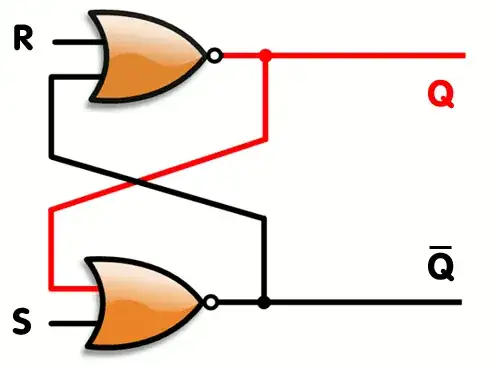
In the R input and S input you can make them 0 or 1.....but what about the input lines next to them (That rely on the output of the R or gate or S or gate)......what do those "Start" out as.

I assume it's Zero.....but with the very first clock signal (To R or S)....it hasn't gotten the output line from the other OR gate yet...so how can it get a first output.

Like lets pretend the first clock signal is R=1 and S=0 ....what about the R or gates input line next to it (that relies on the S OR gates output).....how can it get this on the first "input" signal. It confuses me?

Do we just assume it's zero or what?

edit: Since the question is confusing, the Input line RIGHT below the R (They both go into the top OR gate, im talking about the one right below it). Since it is dependent on the S output....if it's the first "Clock" signal...what would it be set to? Zero? Since obviously it has to wait for the output of S before it can actually be set to anything...but initially what is it considered.

enter image description here

2 Answers2

11

They start out undefined, that is they could be set to either.

When you switch power on, assuming a real latch with no input signals, both gates will want to output high. However due to no two gates being exactly the same (and other real world effects), one will "win" the race to bring it's output high first, and set the others output to low. The same gate may not win every time, so you can't predict the state at power on.

This diagram (from the second link below) helps to visulalise things:

Metastable condition

For further reading about this and metastability, see these links:

Wikibooks SR latch
Latches and FFs
Wiki Metastability
Metastability document

Oli Glaser
  • 54,990
  • 3
  • 76
  • 147
  • I think my question might've been misunderstood. Im not talking about R or S, im talking about the input line next to it. Like The OR gate R is attached to, the line right below it...the input depends on the output of the OR gate S is attached too..if it's the first signal what is the second line (below the R) considered? or maybe im confused at your answer :P –  Feb 10 '13 at 05:27
  • Yes I understood - I'm referring to the outputs/second input of each gate also. If you imagine they were not connected, then on power up both gates would output high (assuming R and S are low). However if they are connected, then both outputs being high at once is not possible. So one has to "get there first", but we don't know which one it will be, so we consider the state of the latch (i.e. either of these other inputs) to be undefined at power on. – Oli Glaser Feb 10 '13 at 06:31
  • @Sauron - I added a few links that may be worth a read. – Oli Glaser Feb 10 '13 at 06:54
  • The lines next to the inputs are the outputs via a feedback path. If you can't guarantee output state, you can't guarantee these either. – Scott Seidman Feb 10 '13 at 13:48
  • Ok Quick question then.....Can a signal still go through an OR gate without the other one connected. (Like could voltage still go through the line R if the one below R hadn't been reached yet?) and you said they'd automatically output to High assuming S and R are low) Why is this? –  Feb 10 '13 at 17:55
  • In case my first question didn't make sense: Imagine an OR gate with 1 input line (Or any Gate for that matter)....can it still go through? –  Feb 10 '13 at 18:00
  • @Sauron - I'm not quite sure what you are asking there. The voltage doesn't really "go through" a gate, the input(s) sets the output to high or low (there is no direct connection). An "OR gate" with one input line is essentially just a buffer, so yes it still "goes through". However the output takes some time to respond to an input change. About the outputting high bit - if the two gates are not connected they will act normally, so if both inputs (of one gate) are low the output is high. I suggest you build a couple of NOR gates in SPICE and simulate things to get an idea of how things work. – Oli Glaser Feb 10 '13 at 20:39
  • @OliGlaser Hmmm, yea what im trying to explain is sorta confusing... the best way I can describe it is think of a Computer being turned on....and lets pretend we are sending a 1 to R and a 0 to S (Keep in mind that the Q/Qnot hasn't even been set yet...since the computer is turned on. How do we get an Initial Output from the gates, since the rely on feedback from the other gate (which hasn't been output yet...since the computer just turned on). Im not talking about a race condition, im confused how we can get an initial output from feedback, if it's the first signal. –  Feb 11 '13 at 05:20
  • I guess what im asking is how we get an "Initial State"...if it relies on feedback from the other gate (and vice versa)...since the lines next to R and S (Sharing the gate) actually haven't gotten anything yet or havent been set to anything. –  Feb 11 '13 at 05:23
  • If you have the R set to 1 and the S to 0 (from a separate power source that shares ground) *then* you apply power to the gate(s) supply pins, the initial state will be as expected (Q low) when the supply settles. The NOR gate only needs one of it's inputs high to set the output low. Essentially this is the same as intialising after power on - you let the gate power up undefined (it could head for either state), then set it to the desired state. – Oli Glaser Feb 11 '13 at 05:48
  • If you think it would help, I'll try and add some simulations to my answer tomorrow. – Oli Glaser Feb 11 '13 at 05:50
  • I think this makes more sense when actually looking at a TTL Logic NOR. http://www.falstad.com/circuit/e-ttlnor.html Since the Voltage is going to go to the output as a High first of all (assuming both input=0).....but then maybe it'll get to one of the transistors faster and then who knows what happens. For some reason I had it in my mind that when a gate isn't receiving BOTH inputs in some fashion....that the input doesn't actually reach it's output. (Which is dumb I dunno why I even thought that lol). If we haven't gotten any feedback output...it's gonna be at 0 (input) for the other gate. –  Feb 11 '13 at 06:20
4

That's the thing with memory devices like flip flops -- you need to initialize them. You can't assume anything about the startup state. If its important to the functionality of your circuit, your power on routine must assert one of the inputs to guarantee a known state.

Scott Seidman
  • 29,274
  • 4
  • 44
  • 109