13

What are these adapters used for?

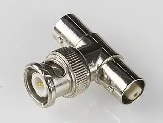
Image of the adapter

(Image off Google, source)

They fit over the tip of a passive oscilloscope probe, like this:

Showing the adapter being placed on the end of a scope probe (Image excerpted from https://www.caltestelectronics.com/public/attachments/GE_series_manual.pdf].)

Why would you want to do that, rather than just running a BNC cable directly to the scope?

Ideas that I could come up with:

  1. The signal must be terminated by a high impedance, and cannot drive the capacitance of an open coax cable. Unlike a length of cable, the adapter is short enough to not produce appreciable standing waves, and also to have negligible capacitance. But if a 50R termination is not allowed, why would there be a BNC connector in the first place?

  2. You can use the 10x attenuator on the probe to measure high voltages. Again, BNC seems like a weird choice for a connector then.

SamGibson
  • 17,231
  • 5
  • 37
  • 58
polwel
  • 1,396
  • 11
  • 27
  • Looking at it again. I'm not sure what you mean. What is this adapter for? The probe cable can't just plug into the scope on its own? – DKNguyen Jul 06 '21 at 14:09
  • The front side of the adapter mates with a female BNC. The rear end fits over the barrel of the probe. – polwel Jul 06 '21 at 14:10
  • What do you mean when you say probe, exactly? A typical passive probe assembly, cable and all? Or something else? I guess I am confused why you need this at all when a regular probe just plugs into the scope. – DKNguyen Jul 06 '21 at 14:12
  • Did you find any data sheet from the manufacturer? Linking to amazon is not very helpful, but it does suggest who the manufacturer might be. Have you followed that trail? – Elliot Alderson Jul 06 '21 at 14:14
  • Ohhhh, it's an adapter for the probe tip, not the probe cable. – DKNguyen Jul 06 '21 at 14:18
  • @ElliotAlderson Multiple companies make these; one has been included with every Teledyne LeCroy scope probe I've ever purchased, and I know you can also get them from Cal Test. I'm pretty sure you can get them from Tektronix and Keysight as well. – Hearth Jul 06 '21 at 14:53

4 Answers4

25

I use these quite a lot. When making a circuit where any high-frequency signals need to be measured with minimal disruption to the circuit, placing a cheap BNC jack as a test point is a very easy way to get a good solid connection to the probe. It also provides better ground integrity than the traditional ground spring (and far better than the grounding clip that's basically an antenna), and better mechanical stability--you can insert the probe and leave it there without it falling over or straining anything on the board. Handy when you have three or four different points that all need to be probed at once, and you don't have three or four hands to hold them all!

If I were to use a BNC cable here instead, the cable's capacitance would create a major problem--I'm trying to measure high-speed events, and adding so much capacitance would ruin the signal. So instead, I use a scope probe, with its high input impedance; 10 MΩ is typical of a 10x probe, with 9 MΩ of that being located right at the tip of the probe. This isolates the cable capacitance from the circuit well enough for the measurements I need to take.


But if a 50R termination is not allowed, why would there be a BNC connector in the first place?

Because I'm designing the circuit, I know I have these adapters handy, and I put a BNC jack there specifically to use them. I usually add something on the silkscreen to the effect of "high impedance scope probe only", because plugging in a cable there would ruin the circuit characteristics.

BNC seems like a weird choice for a connector [for high voltages].

You're right, it is. And that's not what I would generally use these for, though I have used them for high voltages when there was really no other option. It hasn't broken yet, but I'm definitely using the parts outside their ratings. It's an acceptable sacrifice in pursuit of science.
Hearth
  • 27,177
  • 3
  • 51
  • 115
  • I assume you can see my deleted answer about Linear App Note 47, Figure 31 regarding direct connect of a PCB to the scope without a cable, but also without a probe which can also produce a capacitance issue even with no cable present. Can you comment on that? – DKNguyen Jul 06 '21 at 14:22
  • Nice. So, I was on the right track with my idea nr. 1. I was confused why there'd be a BNC jack in the first place, but of course, as a test-point it makes perfect sense. – polwel Jul 06 '21 at 14:24
  • @DKNguyen Connecting directly to the scope isn't an option in my case, where the board needs to be located inside a temperature chamber. I don't exactly want to put a $10k scope into an oven. The board is also far too large with too many distinct test points scattered across it, even if it was room temperature. – Hearth Jul 06 '21 at 14:27
  • I wasn't meaning about mechanical considerations but comparisons rather capacitance introduced by a cable behind attennuation vs no cable but without attenuation. When I wrote that answer I was thinking about a cable-less probe and deleted it when I realized all probes I saw had cables and thought the cable might be too much even behind attenuation. – DKNguyen Jul 06 '21 at 14:28
  • 1
    @DKNguyen The scope itself also has a higher input capacitance and lower input resistance than the scope plus probe--the probe is 9 MΩ on top of the scope's 1 MΩ, and the effective capacitance at the probe tip is, I'm reasonably sure, less than the scope's input capacitance. – Hearth Jul 06 '21 at 14:29
  • 1
    @DKNguyen Yeah, the capacitance of a cable behind a 9 MΩ resistor is very insignificant--as long as the trace leading to your BNC test point doesn't have too high of a capacitance itself! That's something I've managed to mess up before. – Hearth Jul 06 '21 at 14:33
  • @Hearth: An ideal 10x scope probe would behave as a 9 meg resistor in parallel with a capacitance that was equal to 1/9 the combined capacitance of the scope and cable. In practice, scopes offer some capacitance to ground beyond that, but capacitive loading is still reduced a lot even if not by quite a full order of magnitude. – supercat Jul 06 '21 at 22:31
  • Do they not make probe connectors that you could place on the board directly rather than a BNC? – Mark Ransom Jul 07 '21 at 04:15
  • 1
    @MarkRansom They *do*, but I've found they're substantially more expensive than just getting a BNC connector. The fact that BNC is so common drives the price down a lot; I get perfectly good ones from TE that are $2 each in single quantity, whereas the cheapest solder-in probe connectors I can find are $5 each, only come in a pack of 15 or something, and don't look very high quality. The probe to BNC adapter thingy costs a bit itself if one didn't come with your probe, but at least it's reusable. – Hearth Jul 07 '21 at 04:21
  • *"though I have used them for high voltages when there was really no other option"* There *are* high voltage BNC connectors, though (BNC-MHV). They have a longer socket and don't mate with a standard BNC but they are rated for 5kV, generally. – J... Jul 07 '21 at 17:11
  • @J... Good luck finding a PCB mount MHV connector. And one of the main problems with MHV, the reason they're hard to find now, is that you *could* force them to mate with a standard BNC connector. And they only have that 5 kV rating in the mated condition, not the unmated condition. SHV gets around all of these. – Hearth Jul 08 '21 at 00:17
  • @J... Coming back to this because it's been bugging me--I'm pretty sure it's not correct to call MHV a type of BNC connector; it's a different, nominally incompatible connector that's based on BNC. The only things I would consider types of BNC connectors are the 50 Ω and 75 Ω variants thereof. And *maybe* that triax version too. – Hearth Jul 08 '21 at 01:13
  • @Hearth No, it's not BNC, and nor is triax, but it's what you use when you need to connectorize a 50 ohm RF cable for HV. As for PCB mount, you need specialty boards at those voltages anyway, but there are standard ways to connect from panel to the board. – J... Jul 08 '21 at 01:20
  • @J... True, but I was working in a lot of constraints relating to temperature handling and needing to retrofit an existing design. The use of BNC here may not have been the best choice, but it's not blown up so far. It's not kilovolts either; the highest this board is anticipated to be used at is 600 volts, which is higher than you should use BNC for, but not *that* high, comparatively. – Hearth Jul 08 '21 at 01:33
  • @Hearth Yeah, 600V is really borderline. I wouldn't let that out of the lab, or anywhere it needed to be relied upon. As you say, it's not catastrophically under-spec, but it definitely couldn't be certified like that. – J... Jul 08 '21 at 12:06
  • @J... This is purpose-built test equipment that is never going to leave the lab, and will only ever be operated by me personally, or possibly someone trained by me if they end up hiring a technician. Definitely not anything I plan on sell or anything. – Hearth Jul 08 '21 at 13:45
12

One further use: connecting to BNC T-splitters to measure a signal going between two devices:

Connecting another 50 ohm terminated cable would make the total termination impedance 25 ohms, and would in any case cause reflections at the point of the splitter. But connecting a high-impedance oscilloscope probe has minimal effect on the 50 ohm line.

(An alternative way is to connect the splitter directly to oscilloscope input, and run the cable through it to the actual destination. Then the effect of the short branch to the high-impendance oscilloscope input is minimized. But using a scope probe can be more convenient.)

jpa
  • 6,804
  • 17
  • 32
  • Somehow I never thought of this before--good idea! – Hearth Jul 07 '21 at 05:43
  • I can speak for the inconvenience of the alternative method, though I'm usually able to use a (short) BNC cable to the scope rather than having the splitters in the way. – Chris H Jul 07 '21 at 09:32
3

One common use case: Quickly verifying the d... function/arbitrary generator - which might not even be able to drive 50 ohm lines properly; or, you might want to see what it is doing with a high impedance load! - is doing what you think it is doing, without switching your whole probing setup for a 50 ohm terminated cable...

Also: Calibrating probes with some other source than the built-in generator of the oscilloscope.

Peter Mortensen
  • 1,676
  • 3
  • 17
  • 23
rackandboneman
  • 3,085
  • 9
  • 13
1

Why would you want to do that, rather than just running a BNC cable directly to the scope?

If you connect a standard coax to the high impedance input of an oscilloscope, the signal will be reflected at the the connection. This may affect both the circuit being tested and the signal being displayed on the scope. Oscilloscope probes do not use standard coax, but a high loss coax. This high loss coax can connect to the high impedance input of an oscilloscope without causing significant reflections.

More about the characteristics of oscilloscope probe cable can be found in this article by Doug Ford.

Note that some scopes have an optional low impedance (typically 50\$\Omega\$) input which allows the scope to accept inputs directly from coax, for example to monitor a LISN.

Math Keeps Me Busy
  • 18,947
  • 3
  • 19
  • 65
  • I was aware of this. Connecting a coax to the probe (via the adapter) will produce the very same impedance mismatch. – polwel Jul 09 '21 at 08:37