0

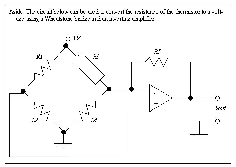
I've bought the chip HC06 (without the breakout board, only the chip itself). I've followed the datasheet and I've done the following connections:

HC06 - Schematic

Datasheet of the chip that I'm using: https://www.olimex.com/Products/Components/RF/BLUETOOTH-SERIAL-HC-06/resources/hc06.pdf

However, when connecting to it via bluetooth, after a few seconds the HC06 always drops conection. Sometimes the LED stops blinking even though there is no device connected to the bluetooth module. At first I thought it was power supply issues, but I've noticed the bluetooth module is being supplied with 3.3 V (which is fine) and the amount of current from the power supply is at maximum 120 mA (not very high, as it is powering up some other modules as well). Any suggestions why it is not working properly?

Update:

I reverse-engineered a HC06 board, and it was following the following schematic:

enter image description here

But even when reproducing the same wiring in my PCB, the problem still persists. So I think the problem is either the chip itself that I am using (might be already buggy) or it is a problem with layout of my pcb.

Samuel
  • 3
  • 3
  • HC06 seems to be a module, do you have a link to the chip datasheet? – Damien Jul 05 '21 at 05:50
  • https://www.olimex.com/Products/Components/RF/BLUETOOTH-SERIAL-HC-06/resources/hc06.pdf – Samuel Jul 05 '21 at 14:24
  • What I'm trying to do is basically reproducing the HC06 module, but I got this problem. – Samuel Jul 05 '21 at 14:50
  • Have you tried adding a WAKEUP on PIO3? – StainlessSteelRat Jul 05 '21 at 18:37
  • Tried to use the wakeup on PIO3 and it keeps disconecting... :( – Samuel Jul 05 '21 at 20:45
  • _"the amount of current from the power supply is at maximum 120 mA (not very high, as it is powering up some other modules as well)."_ - exactly what is the power supply, and what other modules are connected to it? – Bruce Abbott Jul 06 '21 at 00:27
  • @BruceAbbott Besides the bluetooth chip, the output of the voltage regulator is powering up the Max3232ese+ and some LEDs. The power supply that I am using is of 5 V and it can supply up untill 3A, the voltage regulator LM1117T-3.3V is being used as showed on the schematic. – Samuel Jul 06 '21 at 01:09
  • Is 3.3 V stable at all times, even during this problem? Is anything running hot? – winny Jul 07 '21 at 21:57
  • It is stable. I just realized a strange thing though: the resistance between the 5V pin and the 3.3V pin is 33 KOhms. Which is strange, and I don't see why it should be 33 K ohms, but when checking with a voltmeter the voltage seems to be stable. – Samuel Jul 07 '21 at 23:45

1 Answers1

0

Looking at the datasheet on page 6, it shows that pin 22 is connected to ground. It also has a strong external pulldown on pin 11 with (half) a capacitor (C4) to provide delayed power-on reset. And from page 7 of the datasheet, it says that it has a weak internal pulldown on pin 11.

For pin 22, is LED_CON in your schematic the same as GND in the datasheet?

HC-06 datasheet, page 6

HC-06 datasheet, page 7

tim
  • 850
  • 6
  • 13
  • Thanks, I connected the pin LED_CON to ground and I added a 400 nF capacitor to provide delayed power-on reset. I still have the same issue though. :( – Samuel Jul 05 '21 at 23:53
  • Any other suggestions? I can't thinkg anything else besides changing the chip itself... – Samuel Jul 05 '21 at 23:58
  • @Samuel, what about using pullups/pulldowns on all unused inputs to stop them floating? I've used these kind of chips before. They tend to be hit-and-miss whether they work. Cheap enough to replace though. – tim Jul 06 '21 at 00:14
  • @Samuel, what about decoupling capacitors across the power pins? The datasheet doesn't mention anything about them. Perhaps you can reverse engineer an existing board module. – tim Jul 06 '21 at 11:08
  • I will try to do the reverse engineering thing tonight. I'll let you know. – Samuel Jul 06 '21 at 13:24
  • I did the reverse engineering in a board of the HC06. I updated the question showing the schematic of the board that I have here. But the problem still persists. I can't think anything else besides replacing the chip that I am using by a new one (as my circuit is not consuming high current and it follows exactly the same schematic as the HC06 board that I have here with me). – Samuel Jul 07 '21 at 21:38
  • So, I think there might be one of these two things: it is either a problem with the chip I am using or this is problem with circuit layout of the PCB. – Samuel Jul 07 '21 at 21:39
  • I finally replaced the chip and now it works fine. The circuit that I'm using is the one that I presented on the question (after doing the reverse engineering thing). I'm choosing your question as the answer because it was the most helpful one. – Samuel Jul 16 '21 at 22:38