7

I'm doing a log sine sweep to get the frequency response of a device.

enter image description here

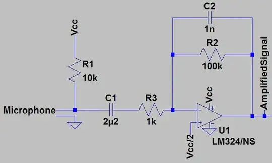
The software works fine, but the first low frequency half period introduces a bit of DC offset in the signal coupling caps, so the DC operating point of the thing moves a bit at the beginning of the signal... and I want to keep the DC operating point stable.

So I was thinking about reversing the sweep, starting with the high frequency and ending with the low frequency. That way the last bit of very low frequency will still cause some leftover offset in the coupling caps, but it'll be after the measurement, so who cares.

Is there any reason why this isn't usually done?

Here's an example of the first half-period interacting with the AC coupling caps in the circuit. The peaks move up and down.

enter image description here

With the waveform reversed in the time domain, it stays centered.
enter image description here

bobflux
  • 70,433
  • 3
  • 83
  • 203
  • 1
    I suspect you'd need to go back a ways to apprehend the full reasoning. I think this is *historical* and relates to the need back then, as well. (They used to use permeability-sweeping, as I recall.) These were perhaps more often used with the old receivers of the time and here, the key requirement is that the amplitude remained dead-flat over the sweep since variations in the generator would be falsely assigned to the receiver as a fault of some kind that really wasn't there. But I'm interested in seeing a good answer on this, too. I'm just not sure anymore, off-hand, thinking back. +1 for Q. – jonk Jul 04 '21 at 22:27
  • An alternative would be to set the initial condition to (say) -0.5V or whatever best cancels out that DC offset. –  Jul 04 '21 at 22:27
  • @user_1818839 but that requires knowing all the details about the highpass transfer function of the signal coupling caps in order to cancel it, whereas reversing the signal just solves the problem... – bobflux Jul 04 '21 at 22:35
  • @jonk yes I suspect it'll be "well we've always done it this way..." – bobflux Jul 04 '21 at 22:36
  • 1
    @bobflux One thing just crossed my mind. These would start at some well-managed starting frequency and chirp upwards to some unmanaged final frequency. (In cases I recall, one such upper limit was in the 250-300 MHz area.) But most of us couldn't afford (or it didn't exist) instrumentation that worked the entire range of the chirp. Two problems then arrive when you start at the high end: (1) the generator starts at the unmanaged end, which probably means it is inconsistent; and, (2) reading the results would be very confusing as the start of the chirp would be mostly useless and problematic. – jonk Jul 04 '21 at 22:43
  • @bobflux Just looking at one of the old Heathkit schematics, I see a pentode operating as a reactance tube (it has an RC at its grid and uses a variable plate current to change its reactance behavior -- much as diodes are used today.) There's an inductor in the plate circuit which forms the continually rising current used to change the reactance. I think this pretty much tells me exactly why these circuits would start out at the low-frequency end. Back then, that was the way to do it. Nowadays, we have more options. – jonk Jul 04 '21 at 22:56
  • As a student, I always used cycle sweeps with a triangle generator or sawtooth for FM and horizontal sweep. But with a bidirectional sweep, it made one direction better than the other. With no storage scope the flicker was annoying, so I would raise the f-min to the breakpoint. So when doing this I had some mental equation relating the ratio of time for DC response and AC duration between fmin and breakpoint, which I've long forgotten since all the spectrum analyzers I used at work would indicate a light if the sweep rate was too fast for accuracy with the span and resolution BW selected. – Tony Stewart EE75 Jul 04 '21 at 23:23
  • My point above was if you relied on a linear sweep trigger above and log sweep for FM with a sawtooth AND you wanted left to right f chart you had to start from f-min. – Tony Stewart EE75 Jul 04 '21 at 23:28
  • @jonk OK, charging capacitor ramp voltage and the high frequency being inaccurate when sweeping a VCO as high as it will go makes sense. I'm using a soundcard, so it's the low frequency that causes problems due to AC coupling though. So the situation is reversed. – bobflux Jul 05 '21 at 06:42
  • @bobflux Sure. But looking at old schematics, I can see a glimmer of a reason why it went the way it did. – jonk Jul 05 '21 at 06:44
  • Why not just keep the LF steady for a couple of seconds (aka as long as is needed to stabilize things) then begin the upwards frequency sweep. – Andy aka Jul 05 '21 at 09:14
  • @Andyaka Because at low frequency, settling takes quite a while, but if I start the measurement from the high frequency, it settles in <1ms since the frequency is high enough to not charge up the AC coupling caps. – bobflux Jul 05 '21 at 10:08
  • I tend to agree with the hystorical inertia motive, otherwise -- whatever works. For example, [here](https://www.beis.de/Elektronik/FreqResp/InstFreqRespMeasure.html) is a method of using a quasi-noise source made of a sum of sines with increasing displacements, which reduces the transients and, thus, the measurement time, while doing it all-in-one. – a concerned citizen Jul 05 '21 at 21:38
  • @jonk I found the answer – bobflux Jul 06 '21 at 18:16
  • @bobflux Yes???? Don't keep me waiting! Oh!!! I see. It's below! – jonk Jul 06 '21 at 18:29

4 Answers4

4

Sweeping from low to high frequency, and from high to low frequency can identify "jump resonances", which are obtained in certain non-linear systems. For example an otherwise linear 2nd order system with a saturation (limit) non-linearity can exhibit different resonant frequencies and different peak amplitude ratios, for increasing and decreasing sweeps.

Chu
  • 7,485
  • 2
  • 14
  • 16
4

I've found the answer.

The frequency of this log sweep signal s(t) increases exponentially, which means shifting the signal in time is equivalent to multiplying its frequency by a constant. For each integer \$ n \$, if the frequency at t is \$ f(t) \$, there is an interval \$ \Delta t \$ such that the frequency at \$ f(t+\Delta t) = n f(t) \$.

After passing the sweep through a device, acquiring the resulting signal, and deconvolving, the impulse response of the device is extracted... which brings forth one interesting property of the log sweep: it also measures distortion, and this manifests as an extracted impulse response that is non zero at negative time.

This doesn't mean the system being measured is non causal. Simply when a frequency f is passed through it, it creates distortion harmonics at 2f, 3f... that look just like they come from the future of the sweep signal.

And that property doesn't work if the sweep is reversed, it can non longer measure distortion.

bobflux
  • 70,433
  • 3
  • 83
  • 203
  • 2
    Cool! And this makes complete sense, too. I learned something today! – jonk Jul 06 '21 at 18:30
  • 1
    This is a nice answer, and this question seems to form: if the reverse log doesn't bring up the impulse response, does that mean that the transient response is avoided and what remains is the steady-state (or close)? Because if yes then reverse log sounds very much promising for plain magnitude/phase measurements. – a concerned citizen Jul 07 '21 at 19:58
  • 1
    Both will extract the same transient/impulse response, the problem I had with the log starting from low frequency was that the low frequency caused some uneven self heating in the devices which upset the bias etc. In the end I just lowered the amplitude. But that makes me think, if the device you want to characterize is like an integrator, with a response that goes off and clips at low frequency, starting the sweep from high frequency and going down could be quite useful. Could even adjust the amplitude in real time. – bobflux Jul 08 '21 at 00:09
  • Where would one start to learn about deconvolving signals with time dependent spectra? – DavidG25 Jul 08 '21 at 18:27
  • @DavidG25 Here's a nice paper: https://hal.archives-ouvertes.fr/hal-02504321/document ; not sure what you mean by time dependent spectra? Deconvolution is just a division between the FFT of the whole acquired signal and the whole sweep. So it's just two spectra, that contain the information about the whole signal. It's very convenient, and since it uses FFT, it's also really fast. – bobflux Jul 08 '21 at 18:43
  • @bobflux by time dependent spectra I meant that the chirp is not a stationary signal, and I am only used to taking FFTs of stationary signals. I think I just need to think about this more. – DavidG25 Jul 08 '21 at 19:15
  • 1
    @DavidG25 if you look at a FFT of a non stationary signal it may not present the information in a human readable way, but if you use FFT as a mathematical tool to perform deconvolution, how it looks is not important, it's just a different way to encode the same information that suits some types of mathematical operations better. – bobflux Jul 08 '21 at 20:27
3

When I have done this for characterizing control systems components, I have used stepped frequency, and I have made sure that each frequency step is held for enough cycles for the transients to have settled out, and then I have actually measured the response.

So the sequence goes:

  • Choose a frequency
  • Hold for some minimum number of cycles or minimum time, which ever is more.
  • Measure for some minimum number of cycles or minimum time, which ever is more.
  • Increment frequency.
  • Repeat as necessary.
TimWescott
  • 44,867
  • 1
  • 41
  • 104
  • 1
    This is fun with machinery that has bandwidths into the audio. "I was wondering if I should dive under a bench" was a not-infrequent comment. – TimWescott Jul 05 '21 at 04:34
0

"With the waveform reversed in the time domain, it stays centered." No it doesn't (well not if it linear anyways), it's just that the wobbles from the low frequency periods occur later (after you cut off the reversed plot), and at a time when there weren't any more peaks for you to add to them to make them look bigger than they were.

Tesla23
  • 2,928
  • 1
  • 3
  • 9
  • Yeah when starting with the high frequency and ending with low frequency, the "wobbles" occur after the measurement is done, which means they aren't a problem. – bobflux Jul 05 '21 at 23:16