3

I have a router that was powered 24h/24. One day the 12 VDC power block died. I made the mistake to replace it with one I get on aliexpress: The aliexpress power block is rated 3 A but when I get it I tested it with a load resistor and it couldn't deliver more than 2 A... I should have been wary. After months of normal use, it started to make some noise. I unplugged it and re-plugged it to see if it comes from the power block. When I plugged it back it makes a big "bzzzz" and the router LEDs went off. I checked the power block output voltage I get 19 V and unplugged it immediately again.

Now on a normal 12 V power block the router leds blink like it restart again and again endlessly.

I would like to see if the router is repairable easily: If the big chips aren't dead. Could you help me to do the analysis? I first wanted to check without power all fuses I could found and test some components like capacitors. No capacitor look exploded.

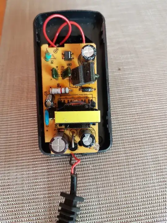
For curiosity one look inside aliexpress power block. Not mutch weight: inside aliexpress power bloc
Front side of router PCB: PCB front side

Back side of router PCB: PCB back side Terrible solder aspect on the back of one chip!

When I opened the router I found a self where a part was missing. I thought it was possible that was causing the problem so I replaced it (I didn't had the same size 4R7 self so I replaced with same value but bigger package): Replaced self 4R7 This doesn't solved the problem, I think this has always been broken because I didn't found the missing part inside.
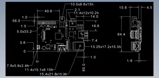
A zoom near the 12 VDC power plug: Near power entrance The RT8285 voltage regulator can work with 24 V so I think it could be still working. I measured onboard the R1 resistor about 16-24 kohms so I guess the output voltage should be 1.8 V according the datasheet tab. The F1 fuse is good (0 ohm). I have a strange feeling with the blue capacitor. I guess it's aim is to protect from high voltage spikes. This one is 0 ohm while other on the board are infinity. But if I try to follow the tracks it appear to be on the same track!? I'm not familiar with multi layers PCB so I can be wrong. Is there a way to check the D5 schottky diode (SM340A) onboard? I couldn't found the datasheet of VR8 voltage regulator.
I found this two components labelled "F2" and "F3" so I guess it could be fuses but I never saw fuses like this : Are this fuses? One is more "passing" (0 ohm) on some tracks than the second.

Sorry for my terrible English, thank for having read :)

ROUGEXIII
  • 177
  • 6
  • 1
    Lesson learned: don’t buy power supplies from Ali and plug it into something expensive. – winny Jul 03 '21 at 18:57
  • what is `normal 12V power bloc`? ... how do you know that it provides adequate current? ... i would suspect the power supply before i start messing with the router – jsotola Jul 03 '21 at 18:58
  • what does this mean? ... `Terrible solder aspect on the back of one chip !` ... which chip? – jsotola Jul 03 '21 at 19:01
  • 1
    Sorry to say but - your router is probably unrepairable. You can test the blue capacitor after unsoldering one lead from the PCB, but I bet it's OK and something else is shorted. Modern RF and LSI chips have tiny transistors in them that do not survive over-voltage. You are probably right about the 4.7uH inductor, and it's probably OK (maybe slightly lower inductance due to the missing bit). Check output voltage of all regulators. Low voltage suggests excessive current draw (fried chip on that rail). High voltage means the regulator is fried (and probably what it is powering too). – Bruce Abbott Jul 03 '21 at 19:22
  • Thank you for all your faster answers :) @winny sure, now I know! – ROUGEXIII Jul 03 '21 at 19:55
  • @jsotola a power supply that was delivered with a similar electronic device from a french serious company. This one is rated 3.15A and is really heavier (the router needs a 2A supply) Of course I checked the polarity too. But you are right I will check the voltage once powered to be sure. – ROUGEXIII Jul 03 '21 at 19:55
  • @jsotola Look the back of the CPU, the solder has a bad look (third photo). But I don't think this comes from the incident. The chips have a cheap radiator so maybe that can explain it. – ROUGEXIII Jul 03 '21 at 19:55
  • @BruceAbbott Maybe, but I have a small hope that all voltage regulator could have a high input voltage range so the output of those don't destroy the CPU or modem chips. Can I first check more things without powering the router? I couldn't identify the voltage regulators VR8, VR9, VR10 and VR11 so I don't know the expected voltage output / output pin. What do you think about components labelled F2 / F3 are they fuses? – ROUGEXIII Jul 03 '21 at 19:56
  • Read my answer. F1 is a 'polyfuse', F2 and F3 are RF filters. Even a momentary voltage increase can be enough to damage sensitive RF and LSI chips. Sometimes they 'melt down' internally enough to cause excessive current draw, other times they just don't work anymore. – Bruce Abbott Jul 03 '21 at 20:07
  • @jsotola you were right, the power bloc output voltage shut down once I plug the router. Something on the PCB must be in direct shortcut. I still suspect the blue capacitor C72 – ROUGEXIII Jul 04 '21 at 12:00
  • I tried to de-solder C72 capacitor, but I break one of its two pins. Anyway the capacitor doesn't seems to be the responsible: between 6.6 and 7.7nF. It is supposed to be 10nF but I think it is fine. Once the capacitor isn't connected to the PCB on one side, the two vias still give 0 Ohms with the multi-meter. – ROUGEXIII Jul 04 '21 at 12:16
  • @ROUGEXIII if you connect a 12 V, high current power supply, such as a battery, then the short circuit will blow out ... do as last resort ... that is how we used to locate shorted bypass capacitors on memory boards many years ago – jsotola Jul 04 '21 at 16:47
  • @jsotola oh :/ what do you suggest to identify the component(s) that is(are) in shortcut without power? – ROUGEXIII Jul 04 '21 at 17:04

2 Answers2

2

I have a strange feeling with the blue capacitor. I guess it's aim is to protect from high voltage spikes. This one is 0 ohm while other on the board are infinity. But if I try to follow the tracks it appear to be on the same track!? I'm not familiar with multi layers PCB so I can be wrong.

EDIT:

Looking closer at the PCB around the power input jack I see that the blue capacitor appears to be connected between the positive and negative power supply inputs. You have removed the capacitor and still get a short, which suggests another component across the power input is shorted. Possible culprits include the 100 uF 25 V electrolytic capacitor next to F1, ceramic capacitors C108, C113, C114 and C406, and VR12. If any of these tests a short you will have to remove it from the board to test it. VR12 is the easiest because you only have to disconnect pin 2, so I suggest checking it first.

Is there a way to check the D5 schottky diode (SM340A) onboard? I couldn't found the datasheet of VR8 voltage regulator.

The diode is supposed to block current flow in one direction, so you should be able to test it with your meter on 'diode test' in both directions. In the forward direction it should drop a lower voltage of ~0.2 to 0.4 V. Diodes usually fail to a dead short. If the meter indicates a short then unsolder one end of the diode from the PCB and measure directly across it.

I found this two components labelled "F2" and "F3" so I guess it could be fuses but I never saw fuses like this :
These are RF filters. They work at a very high frequency so you cannot test them properly with a meter.

Bruce Abbott
  • 55,540
  • 1
  • 47
  • 89
  • thank you for this more replies :) Do you agree it is not possible that the tracks put the two pins of the blue capacitor together? I'm not familiar with multi-layers PCB, must I care something when de-soldering/re-soldering a crossing component? Onboard, with my multi-meter in "diode" position, I get infinite value in two ways for this schottky diode. But as the diode is on the output side of the regulator, I'm not sure it could be damaged? – ROUGEXIII Jul 03 '21 at 20:13
  • It is possible that the capacitor is connected between 2 tracks that are both ground, but there could be another path such as through the antenna cable shield. Vias may connect to internal layers, so you must be careful not to rip pads off the board or pull the vias out. Use a high wattage iron and add 60/40 (not Pb-free) solder to the joint to lower the melting point, and do the job quickly. 'Infinite value' is an open circuit, which is very unlikely for a power diode. It could be damaged by overheating due to excessive load current, but this is also unlikely. – Bruce Abbott Jul 03 '21 at 20:47
  • I de-soldered the schottky diode (hot air station), off board it seems to be normal : Multi-meter + on anode - on cathode : 0.260 | - on anode + on cathode : infinity. My component tester (LCR-T4) gives between 400 and 500mV – ROUGEXIII Jul 04 '21 at 11:30
  • I tried to de-solder C72 capacitor, but I break one of its two pins. Anyway the capacitor doesn't seems to be the responsible: between 6.6 and 7.7nF. It is supposed to be 10nF but I think it is fine. Once the capacitor isn't connected to the PCB on one side, the two vias still give 0 Ohms with the multi-meter. – ROUGEXIII Jul 04 '21 at 12:16
0

Terrible solder aspect on the back of one chip!

Well yes it looks weird, like heavy oxidation. Why all those pins are shorted could be explained by them sitting on the same signal like ground. It's not likely the cause of the problem.

However the rest of the PCB is in poor condition too. There's traces of pollution all over. It could just be flux residue, in which case it is harmless. However, a lot of it looks like splattered solder to me. That's harmful, since it could fall off and cause a short somewhere. It almost looks like residue from wave soldering - perhaps they did the LEDs like that and then didn't clean the board.

Also, PCBs damaged by water tend to look similar to this too... if that's the case, then next destination is the recycling bin.

When I opened the router I found a self where a part was missing.

How did you know that? Were the pads covered in solder or not? Did they look like a component had been soldered to them previously? It could have been left out from the assembly BoM on purpose.

I take it you mean that the coil on the pic was found damaged not missing?

I thought it was possible that was causing the problem so I replaced it

You can't just smack on some seemingly equivalent part there and think it will work. This could be part of some switching regulator in which case the layout and parameters matter a lot. Also you have changed the direction of the magnetic field completely. And this sits next to a RF connector... it better be a fully shielded coil. You could get all manner of strange EMC phenomenon now.

This one is 0 ohm while other on the board are infinity.

Okay so you appear to have a short between + and ground somewhere. It's likely some diode that's blown up, they tend to be the first to go. I wouldn't suspect the caps because if they fail, they tend to do so spectacularly with a little explosion.

The diode and the regulator are the most likely candidates to have blown up. Diodes can be checked by measuring forward voltage with your multimeter. If it's zero, the diode is blown.

I found this two components labelled "F2" and "F3" so I guess it could be fuses

No, the F designator in this case is for filter, since those are RF filters, likely SAW bandpass or such. If you have no reason to suspect they are broken, leave them be.


Overall the board is in a pretty bad condition, possibly worse now than before you started meddling with it. I'd pass it on to recycling.

Lundin
  • 17,577
  • 1
  • 24
  • 67
  • Thank you for your detailed answer :) – ROUGEXIII Mar 28 '22 at 18:10
  • >PCBs damaged by water tend to look similar to this too As far as I know i don't think so. – ROUGEXIII Mar 28 '22 at 18:15
  • > I take it you mean that the coil on the pic was found damaged not missing? Sorry for my inaccurate English. Yes the inductor was damaged, a part of the ferrite is missing and I couldn't find it inside the router. – ROUGEXIII Mar 28 '22 at 18:15
  • > it better be a fully shielded coil Yes I soldered a fully shielded one. Now I have received the identical one, so I can replace it. – ROUGEXIII Mar 28 '22 at 18:15
  • > The diode and the regulator are the most likely candidates to have blown up. Diodes can be checked by measuring forward voltage with your multimeter. If it's zero, the diode is blown. I started to check the diodes (there are not many), they seems fine. I started to desolder / cut the components that have at least 2 pins with 7 Ohm between them (I have 7 ohm between the + and the - pins of the power connector) You were right, the capacitor (C519 and C153) are fine, the first regulator (VR12) is fine, but once I cut the U41 V+ pin : bingo! I order a new AO Z1020AI and cross my fingers :) – ROUGEXIII Mar 28 '22 at 18:20