-1

I have an interesting problem that's been wrecking my brain and would like some help with it.

Basically what I have is a voltage readout box that has a few voltage displays on it. I would like to have a second box with the same set of voltage displays some distance away. What I'm trying to figure out is the simplest way to send data between the two boxes. Also since this is a high voltage and high electrical noise environment I'd like to do it with fiber optic cables. Now I've done this before with things like CAN-bus or Ethernet/IP devices and it works just fine. The issue is that they all require a controller and some level of programming. I'm working with some folks who would like to stay away from programming as much as possible, so I'm trying to figure out if what I want to do can be done in hardware only.

For instance here is a simple idea of how I envisioned this to work:

  • First box has an Analog-Digital converter that reads in the voltage
  • This ADC outputs digital data, let's assume it's 8-bits, on 8 separate lines
  • I take the 8 lines and convert them to optical signal using 8 fiber optic transmitters
  • Take 8 fiber optic cables and run them to the second box
  • In second box I have 8 fiber optic receivers that convert optical input into digital output
  • Digital-Analog converter reads in the data and converts it to analog output
  • Display data on a voltage readout

That sounds fine, except that I need 8 separate fiber optic cables. But if I need to read out 5 different voltages then I'd need 40 cables total, which starts to get ridiculous.

Obviously, the right thing to do is pick some sort of serial transmission that can be done with a couple or few cables. But then I'm stuck with the same problem that I stated above, need to program the thing.

Anyone know of a simple digital communication technique that would allow me to do what I want without having too many cables run between the boxes? The speed of thins thing is not critical, it's all in "human time". Mainly done for safety and monitoring, so a 1 Hz rate is plenty.

Thanks.
Lazyroot
  • 11
  • 1
  • How much is the distance? Yes you are right, 40 fiber optic cables is ridiculous in price when all you need is one. – Justme Jul 02 '21 at 23:59
  • We're probably talking about 10 meters or so. – Lazyroot Jul 03 '21 at 00:10
  • 1
    if you don't need the voltage in digital form, why not just use a small camera? There are plenty of cheap wired and wireless cameras around with small monitors. – Tesla23 Jul 03 '21 at 00:30
  • Important questions are: how easy is it to get data from the existing displays, and what format is it in - this will have a major effect on how you transfer the data to the second location. If the present displays use dedicated voltmeter ICs driving an LED or (especially) LCD displays, it may be very difficult to extract the data you want to transfer. – Peter Bennett Jul 03 '21 at 01:24
  • @Tesla23, funny you should mention cameras. That's what's in place now and I'm being asked to replace it with something more "elegant" – Lazyroot Jul 03 '21 at 02:23
  • @PeterBennett I'm free to get data in any format I want. I have access to "raw" data, which is just an analog voltage 0-10V. I'd like to use a voltmeter display to read and display that data. I can also take the analog signal and deal with it however I wish, right now the plan was to use ADC to get at least an 8-bit representation of it out. – Lazyroot Jul 03 '21 at 02:25
  • Why not a wireless radio solution? – Tony Stewart EE75 Jul 03 '21 at 15:44
  • @TonyStewartEE75: Why wireless? Why introduce the complexity and cost of a wireless system when all that's needed is a reliable way to move a few hundred bits per second a few meters? – JRE Jul 03 '21 at 16:07

6 Answers6

1

If you have easy access to the actual analog signals, the easiest sollution may be to simply pass those analog signals directly to suitable meters in the second location.

Edit: I once designed a system using ADVFC32 voltage-to-frequency converters to transfer signals over optical fiber. The ADVFC32 also works as a frequency-to-voltage converter, so I was able to use the same PC board for both ends of the link. I do have all the design files, unfortunately they are in an old Altium format I can no longer read...

However, look into the ADVFC32 - it may do what you want with no computers. The system accepted and delivered 0 - 10 volt signals. The maximum frequency on the fiber was only 500 kHz

Peter Bennett
  • 57,014
  • 1
  • 48
  • 127
  • I wish I could do that, but we require "no conductor" solution due to safety issues. Behind the wall that's separating the two locations is a 50 kV system with plenty of energy. Normally with something like this I run an ethernet based controller over fiber, but my colleagues are asking me to do something without computers. I told them I'd try my best, but I doubt it will be possible. – Lazyroot Jul 03 '21 at 03:20
  • 2
    if they can afford a 50KV supply, the can probably afford indusrial control equipment like a 4-20mA to optical converter and the reverse. – Jasen Слава Україні Jul 03 '21 at 05:08
  • I think this (voltage-to-frequency) -> (fiber optics) -> (frequency-to-voltage) idea may be the simplest solution indeed. – DamienD Jul 03 '21 at 12:45
  • YES!!!. This is it. Looking at the spec-sheet for ADVFC32 they have an example of fiber optically segregated set of V/F converters. This seems to be the best way to do it and still have a "hardware only" solution. – Lazyroot Jul 03 '21 at 22:05
0

I'd go with SPDIF just because it's easy to implement and not hard to figure out. You'd need two cables and a micro for translation between ADC's

This is a transmitter circuit, not to complicated. And the link shows a receiver Connecting Toslink TORX179L optical receiver directly to S/PDIF coaxial input

enter image description here Source: https://circuit-diagramz.com/optical-spdif-output-schematic-circuit-diagram/

Voltage Spike
  • 75,799
  • 36
  • 80
  • 208
  • S/PDIF is a protocol to transmit audio, I don't recommend it. You can use Toslink optical links for other purposes as well, the common cables, transmitters and receivers with the JIS F05 connectors are cheaply available. – Justme Jul 03 '21 at 00:03
  • My issue is not the optical side of the circuit. I think I have that well handled. I've used Broadcom optical transmitter/receiver to send TTL signal from a pulse generator and it works fine. I suspect I would use similar units to do this work. The problem is that I need something "dumb" that can take a series of hi/lo signals over fiber and convert it to something readable. I can have some sort of microcontroller in place and get it to read some data, but it requires programming. Again I'd like to avoid having to program anything on this device. – Lazyroot Jul 03 '21 at 00:14
  • I suppose the question does not reflect that. Programming a micro to translate serial data is not that difficult. Learning an IP stack is. The ADC requirement of the project *requires* some kind of programming to read the serial or parallel data from the ADC (I am unaware of ADC's that dont use a serial or parallel data bus.) – Voltage Spike Jul 03 '21 at 00:57
  • @Lazyroot How many digits in the displays to be copied -- worst case, I mean. And do the numbers need to be perfectly replicated? Precise to the last digit? – jonk Jul 03 '21 at 01:09
  • @VoltageSpike my issue is not the difficulty of the programming. I'm being asked to make it easy for some "old school" guys who don't do programming. They'd rather edit a PCB then a line of code. I've done a lot of stuff like this in the past and usually I have some sort of a controller, FPGA etc. and program as necessary. I guess my real question is if something like this is possible WITHOUT programming, and from your answer it seems like it's not. Which is fine by me, but I'm not sure if my colleagues will like that answer. – Lazyroot Jul 03 '21 at 02:27
  • @jonk I'm thinking I need an 8-bit representation. Signal is 0-10 V, which gives about 0.04V resolution. Ideally I'd like 12-bit, since in real life that 0-10 V signal represents 0-50 kV, so that 0.04 is about 200 V in real life, which is significant. – Lazyroot Jul 03 '21 at 02:30
  • 2
    Voltage to frequency comes to mind. Just modulate the tx led with the frequency. Simple to recover. For accuracy you could have a reference voltage switched in at a regular interval. Surely there’s an off the shelf solution - 50kV is not kiddy stuff and a significant investment. – Kartman Jul 03 '21 at 03:58
0

Amongst the many solutions to this X-Y problem (I mean, can't you put a ready flashed Arduino in a small box and say it's 'hardware'? If they need to fix it just unplug it and plug in the spare)...

How about five parallel V-F-opto-F-V-voltmeter channels?

  • Low density of links. From your OP you seemed to be happy with 8, unhappy with 40, so 5 should do.
  • All links identical. Spares should any channel go down. Four working ones to compare with any channel that's not working. Swap Tx and Rx ends to determine which is failed.
  • Modest accuracy, reasonable speed.
  • Easy to comprehend what's going on.

Use a 4046 PLL chip for each end. Just the VCO at the transmit end to give V2F conversion. Send a modest frequency over your opto link, so can use the very cheapest grade of opto components. Use the whole PLL at the receive end for F2V. Send the demodulated voltage to a voltmeter. Even use identical boards for both Tx and Rx end, reconfigured with jumpers.

A much tidier solution would be to buy something like an Adafruit PyPortal, only $55, has a large display, and is python programmable. Multiplex your five V2F senders in hardware onto a single optical fibre, with some protocol like pulse length to distinguish the channels (and mux in some calibration GND and V_FSD levels for enhanced accuracy) and then count the pulses and drive the display. Perhaps one off-the-shelf self-contained piece of equipment might convince them to accept programmable stuff?

Neil_UK
  • 158,152
  • 3
  • 173
  • 387
0

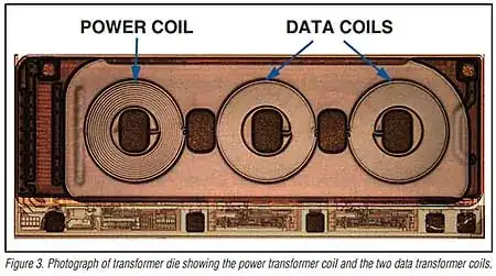
Serdes sounds the answer to me. Both TI and Maxim make the same parts under different part numbers and they are interchangeable. Here's the MAXIM diagram: -

enter image description here

I've used them for combining multiple disparate data streams and then uncombining them at some distance away. Should work just fine with the parallel output of an ADC.

Regards using fibre - no problem with these chips interfacing to fibre drivers and receivers to replace the shielded twisted pair shown above.

Ten lines of digital data are provided by the devices so that leaves a couple spare for any conversion ready line (or a sync line) you might also need to feed to the receiver.

Both TI and Maxim parts are interchangeable.

Picture above from here.

Andy aka
  • 434,556
  • 28
  • 351
  • 777
0

Get your favorite embedded system of choice to interface the meters (Raspberry Pi or similar), run a web server on it that has a CGI interface to the sensors. Then use Ethernet-to-optical for the back haul connection. On the outside you could use any system you want, including some kind of industrial PC with a touch panel, which has a web client to display the data.

If this sounds like ‘programming’ it is. But it will be a lot less effort for a one-off than inventing some serdes protocol.

That said, DMX512 over optical could also do this. This might be more in the spirit of your question. DMX512 is very doable on an Arduino or similar lower-end micro board (yes, ‘programming’ again, but you also said ‘simplest’.) The ‘head’ would be your unit in the HV room, and its ‘universe’ would be the meters outside. Very regular, very predictable, set it once and forget it.

Either way you’ll need to figure out the data acquisition part that works in tandem with the existing meters. To me, that’s the more challenging part of the system given the hazardous voltages involved.

hacktastical
  • 49,832
  • 2
  • 47
  • 138
0

These exist in “low cost” ;) commercial solutions.

I assume you would choose the UNIdirectional 8 ch. but it supports up to 16 analog channels + 32 digital channels BIdirectional with WDM Splitters.

enter image description here

Tony Stewart EE75
  • 1
  • 3
  • 54
  • 182