2

I have a device which will run off a 2.7-60V power source. The voltage may go up to 80V during surges.

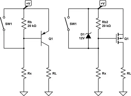
I have a couple of input protection circuits which use N or P channel MOSFETs and require pullups or pulldowns.

Currently I am using a resistor along with a Zener to prevent exceeding the MOSFET VDS. I believe the resistor needs to be chosen to provide at least as much current as specified in the gate-source leakage characteristic plus the correct biasing current for the Zener diode. However, sizing the resistor for operation at 60V means there is not enough current at 3V. Sizing it for 3V means there is too much current draw at 60V.

I would like to reduce the quiescent current to close to 10uA (gate-source leakage.) Is this possible?

schematic

simulate this circuit – Schematic created using CircuitLab

JRE
  • 67,678
  • 8
  • 104
  • 179
  • 1
    Just replace R1 with a low current source that is less than the zener knee current which lowers the voltage ( 10~20% ) as well. – Tony Stewart EE75 Jul 02 '21 at 02:11
  • The issue is all the current source examples I can find have this same issue of increased quiescent current at high voltages as they use a zener for the reference current into the base. – Michael Lawton Jul 12 '21 at 18:08
  • Consider using an LDO regulator. Many have spec'd inputs as low as 3 volts so you might have to see what they do at 2.7, but they almost all have quiescent current in the microamp range. – John Birckhead Jul 12 '21 at 19:03
  • I don't think 80 V input LDOs are available – jp314 Jul 12 '21 at 19:53
  • LT301x, MIC2582 – John Birckhead Jul 12 '21 at 19:59
  • How long does the 80 V last for ? 60 V ? – jp314 Jul 12 '21 at 20:40
  • Continuous voltage shouldn't be over 60V, maybe 65V. 80V is mostly transients in uS range and circuit has a flat-clamp unidirectional TVS (TVS3300,TVS2700 in series) following it which should clamp most transients to around 70V max. – Michael Lawton Jul 13 '21 at 07:45

3 Answers3

2

While 80 V LDOs are not available, you can replace R1 with a JFET with gate shorted to source. This acts as a simple current source.

However, 80 V JFETs are also not available, but you can put two 40 V ones in series. As they approach breakdown, they will share the applied voltage. A part like MMBF4117 may be suitable.

If you are not comfortable with them sharing voltage, you can also put 40 V zener diodes in parallel with each one (and another low value R in series with the whole chain).

jp314
  • 18,395
  • 17
  • 46
  • LT301x are 80V, MIC2582 is 120 volt – John Birckhead Jul 12 '21 at 20:06
  • MIC2582 is 20 V max. LT3011 is 80 V, but has 46 uA IQ and costs $5 in units. – jp314 Jul 12 '21 at 20:39
  • I've only used the LT3014, so you are probably right about the MIC. In our circuit, it draws less than 10-15 uA when lightly loaded. We run it into an input that we set to high impedance when not in use. The datasheet says "7 uA typical with no load," but I'm not sure what good this spec is! We are only running about 45 volts but the spec says 80 with 100 volt transients. You're right about the price - we're paying 10 bucks each for the version we use. – John Birckhead Jul 12 '21 at 22:21
  • High voltage LDOs are actually something I researched extensively for this project. You got the first two numbers of MIC LDO mixed up. Options include MIC5281/2/3 (120V), Seaward Elec SE86XX (60-80V, only 1.8-4uA IQ!), TI TPS7A43 (85V) TPS7A4001 (100V) TL783 (125V), ON Semi NCP781 (150V) and of course Analog LT301X. Using an LDO could work but it's potentially a big and expensive solution and may need protection against reverse polarity. – Michael Lawton Jul 13 '21 at 07:39
  • There are "Current Regulator Diodes" available which are pretty much a JFET with gate shorted to source. However they're only available with current in the mA range and are very expensive. I assumed that it wouldn't be possible to get anything better than that with an actual JFET but I'll look into it. – Michael Lawton Jul 13 '21 at 07:42
  • Some more info (might be better suited to a new question as it wasn't in the original question): I actually have a 3.3V DC-DC where the load is. I can enhance the MOSFET directly with 3.3V or use a charge pump. But the problem with this method is that it is hard to short the gate-source of the MOSFET (used for reverse polarity protection) when input is reverse biased. With the schematic I included it's as simple as placing a reverse biased schottky diode across Vin-Gate. – Michael Lawton Jul 13 '21 at 08:16
  • Here is a good resource I found on JFET current sources: https://www.vishay.com/docs/70596/70596.pdf – Michael Lawton Jul 15 '21 at 12:54
1

Firstly , I’d like to point out that your Gate & Zener to Source are reversed with Drain.

Second , this is by no means an optimal design but rather a paper napkin type of quick and dirty current limiting voltage clamp tested from 3V with an 80V swing.

A Vgs=1V low RdsOn FET was chosen with almost constant current averaging 8uA total bias current over this supply range with a low side DRAIN rise of 13mV @ 1A. Any zener could be used with low leakage. FET gate leakage must be exceeded.

Simulation enter image description here

So there must “Better designed” IC solutions that can integrate these functions.

Tony Stewart EE75
  • 1
  • 3
  • 54
  • 182
  • 1
    I'm not sure if I understand correctly but the Zener is definitely connected to Source in my schematic. The MOSFET symbol is flipped horizontally. It's part of a low side reverse protection circuit. There are some ICs that do something similar (LT/Analog have low IQ and high voltage) but they're all high side. ON Semi has the FR015L3EZ but it's only rated at 12V. This circuit looks promising, I'll have a play with it soon. – Michael Lawton Jul 13 '21 at 07:25
  • @MichaelLawton the Nch source goes to gnd, not the drain – Tony Stewart EE75 Jul 13 '21 at 08:03
  • 1
    They're often used that way, but in this case I only want to block positive voltage/reverse polarity such as if the voltage source was flipped upside down. In normal use the MOSFET should conduct through its body diode until it's enhanced using a circuit like this. – Michael Lawton Jul 13 '21 at 08:09
0

I use similar circuits often, a kind of "better diode". See if this helps:

I try not to switch GND. It can bring you many troubles with other ground in a system, and EMI related issues.

Attached is one I picked from my circuitry, not for 60V, but to explaining purpose. I know it is not a direct answer, but a solution I can think of.

  1. See if you can find a right FET, which has enough high VDS & VGS.
  2. If you found what you like, get rid of the headache, Zener (D4 in my circuitry). Set R33 + R38 > 600K ohm, that is 10uA at 60V. And, set (60 * R33 / (R33 + R38)) < VGS-MAX.

If you find low operating current Zener, that may be added.
Another way to try is adding a current limit / current regulator. A simple BJT can do enough. But, it will be as much difficult as what you are trying to do now, due to the wide dynamic range and low current.
BTW, the zener in my circuitry is at a different side for your purpose.

enter image description here

jay
  • 3,781
  • 8
  • 24
  • Unless I'm missing something this circuit doesn't solve the issue of higher current draw at high voltages. Using resistors for 10uA at 60V would not provide enough current at 3V to overcome gate leakage. – Michael Lawton Jul 16 '21 at 14:59
  • It is an interesting subject Michael. I could not find a FET with uA range gate leakage, mostly are nA. That alone exceeds 10uA requirement. One I can think of is; you may try switching from the source (power source, left of FET) side, it is easier if the source side allows some current – jay Jul 16 '21 at 17:33