4

This question is from a confusion from this thread.

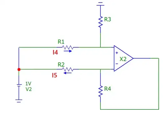
Assume that you have the opamp circuit shown below. Also assume that the opamp is ideal and you don't know the value of R1, R2, R3, R4.

enter image description here

Now you do two measurements:

  1. Apply a voltage 1V between Vp and Vn and you measure the current I1 = I2 = 2.5mA as in the image.

enter image description here

  1. Apply differential voltage V1 = 1V and common mode voltage V2 = 1V as in the image below. You cannot measure the currents I4 and I5 directly. The only current you can measure is I3. Now you look at the ampere meter and see I3 = 1.6445mA.

enter image description here

Question:

Can you calculate the value of I4 and I5 from the two measurements above?

In this post Andy aka calculated it like this:

I4 = I1 + I3/2
I5 = I2 - I3/2

This gives the correct results in that case, but what is the theory behind it?

COMMENT:

What Andy did looks a bit like superposition but actually it is not.

With superposition you would do it as follows:

First you set V1 = 0 and calculate I4, I5.

enter image description here

Next you set V2 = 0 and calculate I4, I5.

Now you notice that the circuit is different from Andy aka's circuit in the first case above as the node Vnis now grounded.

The current through R1, R2 is now not 25mA anymore.

enter image description here

Finally sum I4, I5 from two cases above to get I4, I5 caused by the two voltage sources.

Note that I'm not asking how to calculate voltages and currents at any nodes and branches like what Jan did. I can easily do that using circuit analysis techniques like nodal, mesh analysis, etc.

It seems like everyone misunderstood my question. I'll express it again in the image below.
enter image description here

emnha
  • 1,547
  • 4
  • 34
  • 84
  • 4
    Tip: the ground / earth symbol you are using represents metal plates buried in the ground. They should always be pointing downwards towards the, ehm, ground. – Transistor Jun 27 '21 at 18:59
  • 6
    @Transistor who says that? Or rather, who is going to get bent out of shape by that? – Andy aka Jun 27 '21 at 19:00
  • Anhnha - just so that it's clear, your question is about figuring out what R1 and R2 is and, in reference to my question (that you linked), my R1 equals R2 and that makes a whole heap of difference to a differential amplifier and its common mode input impedance. My intuition in my answer is wholly based on R1 = R2. That needs to be stated. – Andy aka Jun 27 '21 at 19:02
  • 2
    So what's the real question, then? The point made by @Andyaka suggests to me that the lead has been buried in the story. Can you clarify things? Thanks. – jonk Jun 27 '21 at 19:07
  • @jonk are you asking me or Andy? I think my question is clear above. – emnha Jun 28 '21 at 10:44
  • @anhnha If you are unable to see how you may clarify the question, I cannot ask for more than you can understand and provide. (It was for you and not for Andy.) I'm not sure what you are having trouble with, myself. So there it is. Anyway, it looks as though Jan has addressed the obvious. Which may be what you are really asking. If so, you have your answer, I suppose. I thought it might be something more subtle that you were asking, based upon Andy's comment. That's all. – jonk Jun 28 '21 at 16:19
  • @jonk I don't know what is your confustion about my question. I thought it is prety clear. I don't have any problem solving as Jan did. What I asked is completely different. I gave two measurements and then ask if you can calculate `I4` and `I5` from these two measurements. – emnha Jun 28 '21 at 16:24
  • @jonk in Andy post he calculated `I4` and `I5` only based on the information given in two simulations/measurements I mentioned above. The result is correct but I wasn't sure why he could do that. It is not superposition. Now I think it's happenly correct in that case but not a general way to do. – emnha Jun 28 '21 at 16:32
  • @anhnha I believe I only see a general solution here. The tiny complexity being the replacement of constants with variables. Nothing else. It's pretty simple, I think. So I just don't see the confusion, I guess. Even your last comment when you write, "... correct in that case but not a general way to do," is mystifying to me. What do you mean by that? I'm confused even there! Not sure why. But I am. I don't expect you to see my point given what you've written. And I apologize for not being able to see your question better than I'm able now. Sorry. I would give it a shot, otherwise. – jonk Jun 28 '21 at 17:02
  • @jonk it's simple to solve for the voltage and current at any node. However, my question is not about that. I'll try to explain it again. If you read my question above, you'll see that I gave two tests. In the first test, you only apply 1V floating voltage source between positive and negative terminals of the amplifier and you can measure the current through R1 and R2 is 25mA. In the second test, you apply two voltage sources, common mode + differential voltage sources and now in this test you can only measure I3 as in the figure and you can't measure I4 and I5. – emnha Jun 28 '21 at 18:11
  • @jonk now the question is can you find the values of I4 and I5 from the results of these two tests? – emnha Jun 28 '21 at 18:12
  • @anhnha And again, I don't see the problem. If you are able to solve the simultaneous equations, you'd have your own answer staring at you. I don't know the answer right now, but I do know that if I plugged in the equations and solved, I'd be able to tell you one way or the other by a simple reading of the results. I don't see your attempt at the general solution and I don't have time to do it for you right now. But I've no question at all that the answer would be clear from the resulting solution set. – jonk Jun 28 '21 at 18:30
  • @jonk you're completely misunderstanding my question. I don't think I can explain better. As I said it is very simple to solve for voltage and current at any nodes and branches. Just using any circuit analysis techniques such as nodal analysis, mesh or anything else. My question is something more subtle but I'll skip it as I don't think you would get it. – emnha Jun 28 '21 at 18:41
  • @anhnha Okay. Granted. I'll take the hit on this. – jonk Jun 28 '21 at 18:43
  • Tricky. Make a analysis with V1 and V2 with superposition or any other technique. If R1=R2 then I1 + I2 = V1/R1 = constant. From this follows the rest. But I am not sure whether the first circuit with a floating V1 (without ground) is the same circuit. It gives the correct result but it seems more like a trick. – JosefC Jun 30 '21 at 07:30
  • @JosefC I did try superposition and nodal analysis. The thing I wanted to discussion is Andy aka's method. What he used is not superposition but he got the correct result. And in the first circuit, with ground you would get a a different current not 25mA. – emnha Jun 30 '21 at 15:30
  • Sure I get a different current. Because it are different circuits. It must be clear where the differential and common voltage sources are. And an inactive voltage source is shorted. For a calculation set V2 in the second circuit to such a value that in V2 flows no current. Than the currents are the same as in the first circuit. From this point one can overlay the currents. The topic is not so easy. See e.g. the short disucssion in AoE3 p. 354. – JosefC Jul 02 '21 at 06:22
  • @JosefC I editted my question. Hope it is clear now. – emnha Jul 02 '21 at 07:41

6 Answers6

7
A mistake in your question states that 25 mA is flowing; it's 2.5 mA not 25 mA.

Consider this first image (now your 2nd image due to you editing your post): -

enter image description here

This circuit has no forcing CM voltage applied. You see that 2.5 mA flows into R1 and 2.5 mA returns through R2. Because the op-amp creates a virtual-earth, both inputs to the op-amp can be regarded as being at the same potential. For DC considerations this is a very exact approximation and, only op-amp offset voltages and offset currents might make this slightly untrue.

So, given that the currents are the same magnitude (2.5 mA) AND that the op-amp inputs take zero current ideally, we can say, with high-confidence that R1 = R2.

We can also say that the loading impedance on the differential source (V1) is 400 Ω. I don't think this needs explaining given that 1 volt results in 2.5 mA flowing through R1 and R2. And, given that R1 = R2 we then know that R1 = R2 = 200 Ω.

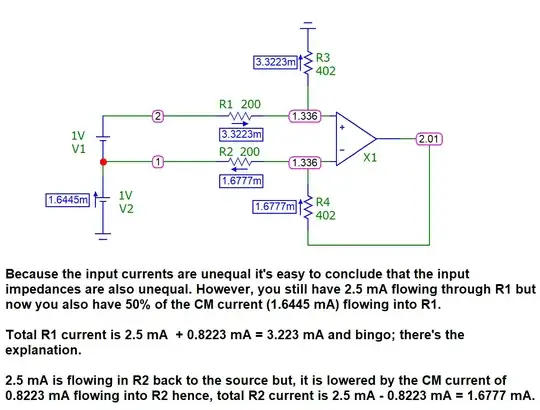
Now, when you push that 1 volt source up a little bit with a forcing CM voltage as per your 2nd (now your 3rd) diagram, extra currents flow from left to right into both R1 and R2 but, the differential currents (the 2.5 mA from above) still remain but, are added to or partially cancelled by the extra currents from the forcing CM voltage.

Your basic question is why the two extra currents flowing left to right through R1 and R2 are equal. Clearly those extra currents add up to 1.6445 mA (your 2nd picture) but, why should an extra 0.82225 mA flow into R1 and why should an extra 0.82225 mA flow into R2.

Firstly, if 0.82225 mA flows into R1 then the impedance seen by the 2 volts at that node has to match 2 volts with 2.5 mA + 0.82225 mA i.e. there has to be an impedance of 602 Ω. And that tells you what R3 is i.e. 402 Ω (because R1 is 200 Ω. And, because this circuit is a balanced differential amplifier we know that R4 must also be 402 Ω.

So, now we have all the resistor values. But we cannot say from the outset what you said: -

Also assume that the opamp is ideal and you don't know the value of R1, R2, R3, R4.

We cannot say that completely because that would not represent a balanced differential amplifier (reference my original post that you are concerned with). And, my original post made that absolutely clear. So, a better thing to say is R1 = R2 and R3 = R4. We must say that because it's a balanced differential amplifier.

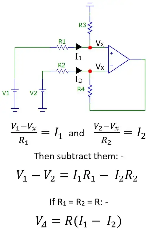
I showed this picture in my original post: -

enter image description here

And, given that the differential input voltage will continue to force 2.5 mA into R1 and take 2.5 mA from R2, it's simple math to see that the two extra currents are equal.


This should be sufficient to demonstrate that the difference in current into the two input resistors is completely due to the difference in voltage applied to the two input terminals: -

enter image description here

It follows from this that the op-amp output voltage is proportional to the differential input voltage when R1 = R2 and R3 = R4.

Andy aka
  • 434,556
  • 28
  • 351
  • 777
  • 1
    The long comment chain has exceeded what is reasonable for comments. Therefore it has been moved to chat and should be continued there (link below). --- As this bulk moving of comments to chat can only be done once, any further comments posted here to discuss the answer, might be deleted without notice. **Keep it in chat, please!** Any updates to the answer which are decided during the chat, should be made via an edit to the answer. Thanks. – SamGibson Jul 06 '21 at 20:48
  • 1
    Comments are not for extended discussion; this conversation has been [moved to chat](https://chat.stackexchange.com/rooms/127257/discussion-on-answer-by-andy-aka-why-does-andy-akas-calculation-work-in-this-ca). – SamGibson Jul 06 '21 at 20:49
3

Here is my method of analysis of this circuit with a floating V1 source at the input.

enter image description here

From this diagram, we can see that \$V_P = I_{IN}R_3 = V_N\$ (due to negative feedback action).

Additional we see that \$V_1 = I_{IN}(R_1 + R_3)\$ and \$V_2 = V_N - I_{IN}R_2 =I_{IN}R_3-I_{IN}R_2 \$

Therefore:

$$V_1 - V_2 =I_{IN}R_1 + I_{IN}R_3 -I_{IN}R_3 + I_{IN}R_2 = I_{IN}(R_1 + R_2)$$ $$I_{IN} = \frac{V_1 - V_2}{R_1 + R_2}$$

Knowing this we can solve for the output voltage

$$V_{OUT} = V_N + I_{IN}R_4 = I_{IN}(R_3 +R_4) =\frac{V_1 - V_2}{R_1 + R_2} \times (R_3 +R_4) = (V_1 - V_2) \frac{R_3 + R_4}{R_1 + R_2} $$

And the gain is:

$$ \frac{V_{OUT}}{V_1 - V_2} = \frac{R_3 + R_4}{R_1 + R_2}$$

But due to the fact that we want CM gain to be equal to \$A_{CM} = 0\$ we need to meet this condition \$\frac{R_4}{R_1} = \frac{R_3}{R_2}\$. Thus, \$R_4 = R_3\$ and \$R_1 = R_2\$. So we can simplified the gain expression to:

$$ \frac{V_{OUT}}{V_1 - V_2} = \frac{R_4}{R_2}$$

Now if we add a CM source to the circuit we have this new situation.

enter image description here

And because we have a linear circuit we can try to apply the superposition principle. To find \$I_3\$.

enter image description here

$$I_3 = I_4 + I_5 = 2 \times \frac{E_2}{R_1 + R_3}$$

We assume \$A_{CM} = 0\$ and \$R_4 = R_3\$, \$R_1 = R_2\$

$$I_4 = \frac{I_3}{2}$$ $$I_5 = \frac{I_3}{2}$$

And finally

$$I_{R1} = I_1 + I_4 = I_1 + \frac{I_3}{2} $$

$$I_{R2} = I_2 - I_5 = I_2 -\frac{I_3}{2} $$

G36
  • 13,642
  • 1
  • 18
  • 33
  • The long comment chain has exceeded what is reasonable for comments. Therefore it has been moved to chat and should be continued there (link below). --- As this bulk moving of comments to chat can only be done once, any further comments posted here to discuss the answer, might be deleted without notice. **Keep it in chat, please!** Any updates to the answer which are decided during the chat, should be made via an edit to the answer. Thanks. – SamGibson Jul 06 '21 at 20:45
  • Comments are not for extended discussion; this conversation has been [moved to chat](https://chat.stackexchange.com/rooms/127255/discussion-on-answer-by-g36-why-does-andy-akas-calculation-work-in-this-case). – SamGibson Jul 06 '21 at 20:46
3

This answer is only for the problem with the superposition to calculate the currents.

Superposition for two voltages is typically done with the cases \$(V1=0, V2)\$ and \$(V1, V2=0)\$.

But that is not necessary.

It can also start from any known \$(V1, V2)\$ with the cases \$(V1 + \Delta V1, V2)\$ and \$(V1, V2 + \Delta V2)\$. This follows clearly from the linearity of the circuit.

E.g. \$ I1 = A*(V1 + \Delta V1) + B*(V2 + \Delta V2) \$

There is surely a book with a proof.

Assume R1=R2. I1 flows to the right. I2 flows to the left. Vx is the voltage on the Opamp inputs.

We start with the differential circuit. That is without the CM voltage source V2 (really removed).

Like all have shown

$$I1 = I2 = \frac{V1}{(2*R1)}$$

Now calculate the voltage at the bottom of \$V1\$. I call it \$V1n\$.

$$ V1n = I1*(R1+R3) - V1 = \frac{V1}{2*R1} * (R1+R3) - V1 = V1*\frac{R3-R1}{2*R1} $$

Set the value of \$V2\$ to \$V1n\$ and connect it to the circuit. The two circuts are equivalent, because the voltages and the currents are the same. Through \$V2\$ flows no current.

Now increase \$V2\$ by \$ \Delta V2 \$ to its final value. Here it is \$ \Delta V2 = 1V - V2 \$.

This is the superposition but only with a change of \$ \Delta V2 \$. The calculation can be done only with the \$ \Delta's \$ in the circuit.

$$ \Delta I1 = \frac{\Delta V2}{R1+R3} $$

$$ \Delta Vx = \Delta I1 * R3 $$

$$ \Delta I2 = \frac{\Delta Vx - \Delta V2}{R2} $$

Alltogether gives

$$ \Delta I1 = - \Delta I2 $$

The rest follows.

Hope there is no big error.

JosefC
  • 256
  • 1
  • 5
1
  • Superposition will always apply if the 2 critical specs are met, namely; Vcm input and Vout are both within the linear range
  • Vdiff to the OP Amp is always 0V and Vcm only rises to some ratio of the V2 = applied.
  • The Idiff currents I1, I2 remain the same and reject the common mode current applied as you expect from CMRR.
  • Thus you expect the new Idiff currents (I1,I2) to be raised by the Icm (I3) applied
  • although the Voltage across R1,R2 is always equal they are not necessarily equal current magnitudes (given that all R values are unknown)
  • !
  • the single ended currents have changed by Vcm being added, and the resistors values are unknown, you cannot assume they are split equally by 1/2. Thus the new I1,I2 are unknown. The other answers are fallacious because by example they assumed equal R’s.

The bottom line is that the output voltage now has an error if the resistors pairs (R1=R2, R3=R4) are NOT equal, when any common mode voltage is applied (AC or DC).

Even though the differential current remained constant any tolerance errors in this match affect the CMRR and results in a conversion to an error in the output voltage to compensate for the change in single ended source currents with negative feedback.

——

If we assume a balanced R ratio for diff gain and balanced sum for each leg for CM rejection, we can explain this without math.

Since R1 & R2 are terminated with a null difference voltage, the current loop is always constant as long as the linearity conditions are met. The added current from Vcm=1V will see the Thevenin Equivalent resistant of both equal branches (R1+R3=R2+R4) in parallel so V2 must supply twice the added current or in other words each branch splits the V2 input current equally.

Tony Stewart EE75
  • 1
  • 3
  • 54
  • 182
1

Nota : the two circuits are "different" ... so superposition can't be applied, even if results can be correlated.

Theoritical assumptions ... All Rx are equal. OPamp : Uplus = Uminus

First case : U1 = 1 ; IR1= U1/(2R1) ; IR2 = U1/(2R2) ;

Second case :

U1 = 1 ; U2=1 ; Up = (U1+U2) ; Uplus= Up / 2 = 1V ; I3 = I'R1= (U1+U2) / (2*R1) = 2 *IR1 ;

As inputs of OPamp are at same level ... I5 = I'R2=0 ;

So I(U2) = I3 = 2 * IR1

-> I5 =I'R1= I3 /2 + IR1 ; I4 = I'R2 = I3 / 2 - IR1 = 0 ;

Unless I made a sign error ...

If R3 = k * R1 ; R4 = k * R2 ... and I4-(-I5) = constant= 2 * I1.

The resistance of ammeter is not taken into account !

In fact, it is more simpler ...

case 1 : I1 = I2 -> I1 - I2 = 0 but I1 - (-I2) = 2 * I1 (always)

So (node between U1 and U2) (eq 1) I4 = I3 + I5 and (eq 2) I4 - (-I5) = 2 * I1 (constant)

Solving (1) and (2) give :

adding (1) and (2) -> 2 * I4 = I3 + 2 * I1 -> I4 = I3 / 2 + I1

substracting -> I5 = - I3 / 2 + I1

For request of someone ...

Adding Math sheet picture : Maple software

In picture I forget ... adding_currents ... # C = i1 + i2 := 2 * i1 ... which is constant !!!

enter image description here

Adding Microcap circuit picture for Dynamics DC Analysis

enter image description here

Antonio51
  • 11,004
  • 1
  • 7
  • 20
  • Could you try to write your answer with proper math notation by using $? What you have written here looks very interesting but I don’t quite understand it due to the poor formatting. – Carl Jul 05 '21 at 11:56
  • 1
    Sorry ... I only use Maple software ... I add math sheet picture and another picture to show using microcap12 Dynamic analysis ... I hope no errors ... :) – Antonio51 Jul 05 '21 at 16:06
  • Everyone knows that the "classic" differential amplifier is not "dependent" on a "common mode voltage" (or if one prefer ... the addition of a "potential" to the initial system ) and therefore that the operation of this circuit does not change since the operational amplifier reacts to any "disturbance" accordingly. I really want to write ... that it is a "general relativity problem" ... :) My "constant" is only dependent of (R1+R2) ... not R1 or R2. – Antonio51 Jul 06 '21 at 05:41
0

In general, I4 or I5 varies upon R4, R2, R3, and R1. Thus, with given information, I4 & I5 are not deterministic.

a) In the circuit of "1.", we can close the circuit at the OPA input node, Vcm. Since I1 & I2 includes all the current;
I1 = I2 = (Vp-Vn) / (R1 + R2).This resolves in:
(R1 + R2) * (2.5mA) = 1V ---(1)

b) In the circuit "2.",
I3 + I5 = I4, I3 = I4 - I5, Thus,
I4 - I5 = 1.6445mA ---(2)

c) Meantime,for the same sense as "a)",
V1 = I4 * R1 + I5 * R2 = 1V ---(3)

While solving for I4 & I5, along with two other variables (R1 & R2), I could not come up with another set of equation (too lazy :-).

However, the solution exists when the resistor sets are consisting a differential amp with balanced impedance,
R1 = R2 ---(4)


Question 1: "Can you calculate the value of I4 and I5 from the two measurements above?":
Answer: 'No', for general solution, 'Yes', with another condition provides an unique and proper equation. That another condition was "differential amp with balanced impedance", then;

I1 = I2 = 1 / (R1 + R2) --- (1)
I3 + I5 = I4 --- (2)
I4 * R1 + I5 * R2 = 1V ---(3)
R1 = R2 ---(4); "differential amp with balanced impedance"

Question 2: "Andy aka calculated it like this: I4 = I1 + I3/2, I5 = I2 - I3/2"
Answer: As explained, "differential amp with balanced impedance" was assumed to come up with that equation.
When R1 == R2 (balanced impedance), from eq(1),
R1 = R2 = 2 x I1 = 2 x I2 --- (1.1)

Substituting eq(1.1) to eq(3),
I4 + I5 = 1/(2 x I1) = 1/(2 x I2) ---(3.1)

Rewriting eq(2),
I4 - I5 = I3 ---(2.1)

eq(3.1) + eq(2.1) => I4 = I1 + I3/2 ---(Andy's 1)
eq(3.1) - eq(2.1) => I5 = I2 - I3/2 ---(Andy's 2)

jay
  • 3,781
  • 8
  • 24