1

schematic

simulate this circuit – Schematic created using CircuitLab

I am simulating a circuit in LTspice in which I use an aluminum electrolytic:

C=100µF, Rser=0.25, Lser=5n

Due to some other components, I now see an L-C resonance at several GHz in AC simulations, which runs through the L of the electrolytic and small parasitic C of some other components, effectively about 1 pF.

enter image description here

From experience, I know this is absurd. An aluminum electrolytic doesn't participate in such high frequency resonances. Its series resistance seems to be very large at high frequencies and in fact I use them to damp resonances.

How can I tune the circuit model of the electrolytic capacitor to get a more reasonable high frequency behavior?

Merely raising the series resistance makes it useless at normal frequencies of course. Is there a comprehensive way? (For example, multiple components or other methods.)

(Might be related)

Voltage Spike
  • 75,799
  • 36
  • 80
  • 208
tobalt
  • 18,646
  • 16
  • 73

1 Answers1

1

I don't know where you are seeing the pole past 1GHz, here is my sim:

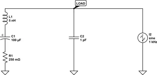
I did add some series resistance on the voltage source, because in the physical world you'll have at least 10mΩ on any source.

enter image description here

One thing that could be happening is cshunt could be changing things (it adds a capactior to ground on every node, which is more realistic for a PCB as each trace will have some capacitance to a ground plane if you have one in your design) Also the above plot is with cshunt disabled, in the one below cshunt is 1pf. One problem also would be the return path inductance/resistance to the source which would need to be modled. Also I would suspect you would need transmission lines to carry any kind of GHz bandwidth.

enter image description here

When all is said and done GHz get's filtered out pretty quick in the real world as any kind of copper has parasitic inductance and that would impede GHz signals

If you are looking at the GHz+ range, you would probably want to model each element of the capacitor and its capacitance to a local plane on the PCB, I kind of did this in this answer here. Why does Samsung include useless capacitors?

(and take each volume of the capacitor and PCB and come up with a parametric model for the whole capacitor) YMMV because materials also make a difference so it would probably be best to analyze it with a network analyzer or GHz source (which I have no experience with).

Edit:

One interesting thing is adding ESR and ESL of the wire with cshunt and I did get the frequency to 'pop'.

While I think you could get some resonance on the PCB, I think you'd have to get a much detailed model (the input from the voltage source needs to be a waveguide/transmission line because attenuation would sink most GHz signals)

enter image description here

here is also this one where cshunt is negated and I added in two 1pf caps and it looks much more normal, the real world could be somewhere in between the model above and below enter image description here

Voltage Spike
  • 75,799
  • 36
  • 80
  • 208
  • Ive added a CircuitLab sim to the opening post, which shows the resonance at a few GHz. I think cshunt works differently, because it puts a C from every node to GND. But I guess, this by itself shows already that the GHz resonance is nonsense, because there is stray capacitance everywhere. So cshunt makes more sense than only some elements having stray capacitance. – tobalt Jun 24 '21 at 17:23
  • One problem with the circuitlab sim is that cap cannot be physically constructed and should also have some series resistance and inductance associated with it, when modeling things in the GHz range any piece of copper will make a difference. Another problem is wavelength also becomes an issue so FEM's make more sense. – Voltage Spike Jun 24 '21 at 17:36
  • With the circuit lab sim you also need some series inductance and resistance on the source which will also create a pole in the GHz range – Voltage Spike Jun 24 '21 at 17:37
  • Right.. so in a nutshell. At sub-ns, a PCB-level spice sim that doesn't put effort into simulating parasitics well loses much of its merit? – tobalt Jun 24 '21 at 17:57
  • It's up to the designer to know how much parasitics they need to simulate and what and how. If you are in the DC to 1MHz range, for most designs parasitics don't mean that much (if your doing a DC DC converter then they usually make a difference). The hard part is knowing how much of the real world you need to simulate to make an accurate model, and anything after 1GHz is difficult to model, because pf, nH's and mΩ's all make a difference. – Voltage Spike Jun 24 '21 at 18:10