11

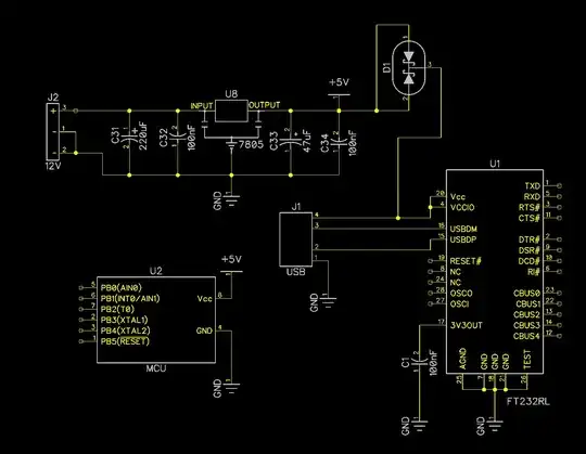
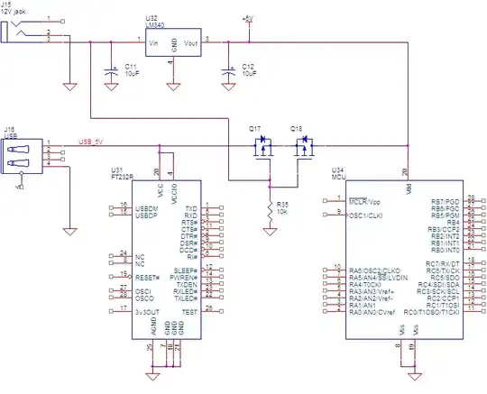
There are two power supply sources in the following diagram - USB and 12V. Only one power supply can be connected at the same time. I am trying to disable power to FT232 whenever 12V is plugged in. In that case FT232 should not be powered, but MCU will be powered. However, when USB is connected, both FT232 and MCU should be powered. I tried to use Schottky diodes(BAT54C) but I'm not sure if this is correct way.

Also - would USB power harm voltage regulator in the second case?

enter image description here

Nick Alexeev
  • 37,739
  • 17
  • 97
  • 230
Pablo
  • 1,551
  • 3
  • 20
  • 41
  • 1
    I'm not certain, but simply changing how D1 is oriented would work, minus the diode forward voltage drop. Connect pin 2 of the diode to the regulator output, pin 1 to the USB VCC, and pin 3 goes to the MCU VCC and other parts. This way the MCU gets powered no matter what, while the FT232 is only powered by the USB power. The Diodes would provide reverse current protection so that the USB vcc never shows up on the regulator output, and the regulator never shows up on the usb vcc line. And only the higher voltage diode would show up on pin 3, even if you connect both usb and 12v jack. – Passerby Feb 06 '13 at 05:23

1 Answers1

8

Your schematic seems to have a bug. If you apply +5V from USB, then D1 is reverse-biased, and μC wouldn't get +5V.

Here's what I can propose instead. Of course, this is just a rough diagram, which shows only power distribution.

enter image description here

FTDI chip is bus powered only always.
When +12V source is not present, the gates of Q17 and Q18 are pulled low and the +5V rail is powered from USB.
When +12V source is present, the gates of Q17 and Q18 are pulled high and the USB section is not self-powered from the +12V supply.

MOSFET body diodes are the reason for having two MOSFETs back-to-back instead of just one. This is to prevent the USB host from getting back-powered.

Nick Alexeev
  • 37,739
  • 17
  • 97
  • 230
  • thanks. Having max 100-200mA load on MCU circuits, could you recommend me MOSFET body suitable for your solution? – Pablo Feb 06 '13 at 10:32
  • I don't see in the schematic how the USB 5V can power the MCU. Moreover, it still shows N MOSFETs instead of P MOSFETS. – igorsales Aug 29 '17 at 02:40
  • @igorsales It does not show N-MOS. – Asmyldof Aug 29 '17 at 09:15
  • @Asmyldof I'm sorry, my mistake. However, I still cannot follow how current flows from the USB 5V to U34 when 12V isn't applied. Would you mind explaining? Many thanks. – igorsales Aug 30 '17 at 00:45