3

I have problem driving a high current DC motor (RS-775 24V-12V 80W), the MOSFET getting very hot when I use PWM signal.

I'm using Raspberry Pi 3 b+ to generate PWM signal at (pin 8) which connected to MOSFET gate through 1 kΩ resistor as the schematic shows:

schematic

simulate this circuit – Schematic created using CircuitLab

Notes:

  • The threshold voltage of IRF3205 is between 2-4 V and the Raspberry Pi gives signal of 3.3 V that will be fine (i thought...)
  • The datasheet shows that the MOSFET can handle Id = 110 A
  • Rds =8 mΩ

Tests :

  • Without load every thing works good, motor spin very fast with current < 2A, no heat at MOSFET.

  • When I tried to run the motor with load at 6 V it consumes about 8.6 A and there was the problem MOSFET and Flyback diode goes very hot!!
    First I tried to use 3.3 to 5 V converter to amplify the PWM signal to 5 V but this made things worst the MOSFET getting hot faster than before.

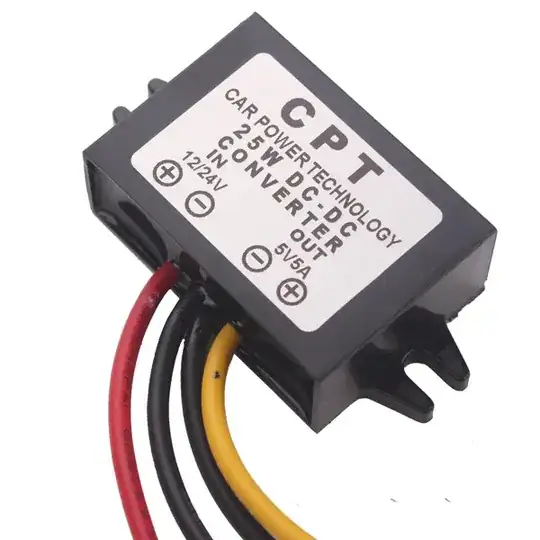
3.3 V to 5V logic level converter photo:

enter image description here

As a test I removed the PWM signal wire from gate and use the V+= 5 V instead , the motor spins and the MOSFET has a reasonable amount of heat.

Here is the schematic:

schematic

simulate this circuit

Conclusion : The reason of the heat is the PWM itself, the ON/OFF effect is the reason of the heat.

This is my opinion, and any one have other explanation or solution to the heat I hope he answers.

Thanks.

0ussama
  • 111
  • 1
  • 6
  • 1
    What is the PWM frequency? – Bruce Abbott Jun 16 '21 at 00:50
  • Why are you using a 24 volt motor with a 6 volt power supply? – Hearth Jun 16 '21 at 01:34
  • @Hearth this an application for Pov display , with 6V voltage i get about 1782 RPM it is enough for my project which needs only 1500 RPM – 0ussama Jun 16 '21 at 02:35
  • Your gate drive is not enough, the data sheet for the MOSFET will let you know how much gate voltage you need. It is normally in graph form. Also move your 20K resistor to the other side of the 1K resistor which you will replace with something in the 100 ohm range. That may cool it down a bit. – Gil Jun 16 '21 at 02:38
  • _"PWM is square wave signal , it has frequency and also duty cycle"_ - which tells us nothing, but in another comment you said it was 15kHz so... – Bruce Abbott Jun 16 '21 at 02:38
  • Yes it was 15khz then i changed it to 1khz which made the mosfet little less hotter than before – 0ussama Jun 16 '21 at 12:11
  • Why 1 kohm gate resistor? – winny Jun 16 '21 at 13:43
  • 1
    _"The threshold voltage of IRF3205 is between 2-4 V and the Raspberry Pi gives signal of 3.3 V"_ A recipe for disaster. Choose a different MOSFET or get yourself a MOSFET driver. – winny Jun 16 '21 at 13:47
  • @winny https://electronics.stackexchange.com/a/68754/289063 – 0ussama Jun 16 '21 at 14:19
  • Yes, but why 1 kohm? – winny Jun 16 '21 at 14:21
  • @winny i don't know , all i know is i must put resistor at mosfet gate for the reason mentioned in the link above. – 0ussama Jun 16 '21 at 14:38
  • Ok, you are out on thin ice. I would recommend doing more simulations and read up on the subject before you continue. – winny Jun 16 '21 at 14:42

4 Answers4

14

The threshold Voltage of IRF3205 is between 2V-4V and the Raspberry Pi gives signal of 3.3v that will be fine

No. Gate threshold is where the MOSFET barely starts conducting. So if it varies between 2-4V and you are applying 3.3V you are at best barely turning it on and at worst you aren't turning it on at all. You use at least the Vgs listed to get the rated RDson in the datasheet. You should be applying a Vgs of at least 10V.

Ignore Vgsth when using MOSFETs as a switch.


You also need a gate driver which does three things:

  1. Supplies more current than your GPIO
  2. Supplies more voltage than your GPIO if the MOSFET gate source requires it
  3. Allows your low-voltage, low-current GPIO to control the two above.

Your GPIO can't sink or source enough current to charge/discharge the gate-source capacitance fast enough so what is happening is that your MOSFET is spending too long in the inefficient transition region between conducting and blocking where it acts as a moderate value resistor. When blocking, there is lots of voltage across the MOSFET but no current so no heat. When conducting there is lots of current through the MOSFET but little voltage across it so little heat. During the transition region there is moderate/lots of current through the MOSFET and moderate/lots of voltage across the MOSFET so LOTS of heat.

If you just switch the MOSFET on and off occasionally, you can get away with direct drive from GPIO (if the MOSFET is logic level, yours is not) since time spent in the transition region is very small fraction of the overall operating time and there is plenty of time to cool down. But when you're PWMing you're switching thousands of times per second you are entering the transition region just as often.

You can buy gate driver ICs or you can make your own from discrete transistors in push-pull or totem-pole configurations

  • if you choose to use MOSFETs in the level shifter they need to be logic level or else you will obviously run into the same problem you are trying to solve
  • as drawn below, the PMOS must have |Vgs max| > 10 or 15V since that is what it will be when its gate is pulled LO by the GPIO. Otherwise zeners and resistors to clamp the PMOS Vgs to tolerable levels need to be added.
  • You want these MOSFETs to be small so they have low gate-source capacitance and can respond quickly to the weak GPIO.
schematic

CORRECTION FOR SCHEMATIC ABOVE: 1MOhm resistor on gate driver input should be pull-up, not pull-down. Website has glitched out and I can no longer edit the schematic.

In the level-shifter, a current source or active pull-up (made of transistors) will be faster than a pull-up resistor since no RC time constant which will in turn switch your gate driver MOSFETs more quickly (if you are using MOSFETs in the gate driver stage).

The 5 Ohm resistors are there to limit shoot-through since both gate driver transistors are being driven by the same control signal so there is no guarantee they won't both be moderately conducting as one turns off and the other turns on.

Depending on the details of the transistor you are using and how the drive for them exactly turns out, you might be able to remove the 5 Ohm resistors and just tolerate the shoot-through current if it is small and fast enough.

Another way to deal with shoot-through (when using MOSFETs in the gate driver at least) is to use diodes to route the gate current paths through different components during gate-source capacitance charge and discharge so that the turn off time is faster than the turn on time. This doesn't work with BJTs whose control depends more on base-emitter currents than base-emitter voltage. By the way, this approach works for power MOSFETs in half-bridges and H-bridges as well where you can't use any other shoot-through handling methods mentioned in this answer which rely on throttling power (makes too much heat for high powered circuits). My opinion is you should just use independently controlled gate signals in that case, but for gate drivers no one wants that extra complexity.
schematic

simulate this circuit – Schematic created using CircuitLab

You can also swap the positions of the NMOS/NPN and PMOS/PNP of the gate driver stage for a configuration with no shoot-through. This makes them act as source/emitter followers, more like amplifiers with a controlled crossover rather than switches. This then allows you to remove the 5 Ohm resistors which are only there to limit shoot-through currents which prevents them from limiting the current charging/discharging your power MOSFET gate-source capacitance. But the price you pay for this is that they won't reach the rail voltage as closely, but without those resistors they will traverse the middle region more quickly.

schematic

simulate this circuit

DKNguyen
  • 54,733
  • 4
  • 67
  • 153
  • Thanks for your reply . i tried to lower down the PWM frequency to 1000 Hz instead of 15 Khz this is made the heat goes down little especially with low Duty cycle , I'll see what can i change next . But Recently i found that Flyback diode is getting hot too ! – 0ussama Jun 16 '21 at 01:23
  • 5
    @0ussama No, you *need* to use a gate driver to drive the FET at a higher voltage. 3.3 volts is *not* enough to turn it on, you're misunderstanding what the threshold voltage is. The FET is getting hot because it's not turned on fully. – Hearth Jun 16 '21 at 01:35
  • @DKNguyen Your drivers you drew are both not going to work very well; you've put an emitter follower and a source follower when what you need is a switch. – Hearth Jun 16 '21 at 01:36
  • @Hearth I am aware. Just simpler this way because then OP won't need to worry about shoot-through in the gate driver. – DKNguyen Jun 16 '21 at 01:39
  • @DKNguyen But this won't give any higher voltage than the microcontroller can already output. – Hearth Jun 16 '21 at 01:40
  • oh wait I see what you mean. Yeah. – DKNguyen Jun 16 '21 at 01:40
  • @Hearth PWM frequency can increase the heat because the higher frequency you set the higher transition region you get which the cause of heat in first place . can you tell me how i can calculate Vgs voltage from datasheet to turn the mosfet on fully – 0ussama Jun 16 '21 at 01:52
  • 1
    @0ussama I already told you in my answer how to get it. In fact, I also outright told you what it should be. – DKNguyen Jun 16 '21 at 01:53
  • @DKNguyen thanks . – 0ussama Jun 16 '21 at 02:00
  • @0ussama Yes, PWM frequency will affect things, but the FET not being fully on will be much worse for the heating than anything else. – Hearth Jun 16 '21 at 02:23
  • @Hearth yes ofcourse – 0ussama Jun 16 '21 at 02:37
  • Why are the 5 ohm resistors needed in the gate driver? – Tejas Kale Jun 16 '21 at 08:49
  • 2
    @TejasKale See the last few paragraphs of the answer. It is because of shoot-through. This very much comes up in H-bridges and half-bridges in converters where currents are high but you cannot tolerate losses of resistors. – DKNguyen Jun 16 '21 at 13:38
2

You cannot use 1kR resistor on the gate!! I mean, you can, but then the MOSFET turns on and off slowly, therefore having non-zero power for a longer time in the cycle. And heats up... Use voltage of 5-10V and smaller resistor. Or lower frequency.

2

Other suggestions are correct but for immediate improvement find a “logic level” fet that can operate with 3.3V gate drive. They’re not the best but they exist.

Change the 1k to <100 ohms and the 10K to 100K or remove it (the divider shown is slowing down the gate drive and dropping the gate drive voltage even further).

asdf30
  • 69
  • 2
0

To answer the other half of the question, you could use a Schottky diode (with an appropriate current rating) as the flyback diode to reduce its temperature. The idea being that the lower potential difference across the Schottky diode will result in lower current x voltage heating.

You could add a small-value resistor* in series with the diode to share the heat dissipation which would otherwise be shared between the diode and the motor windings.

* Determining a suitable value and power rating is left as an exercise for the reader.

Andrew Morton
  • 2,389
  • 1
  • 17
  • 26