0

I have a variable voltage called Vreg (Voltage regulated) which is output of switching regulator (buck converter) and is less than 12v.

Also there is ANALOG Signal with voltage between 0 < V < Vreg < 12v. (Vreg is less than 12v). I need to scale my ANALOG signal from 0 < V < Vreg span to 0 < V < 5v span so that I can read it directly with Arduino. Also need it be economic with few parts or easily available parts like very common op-amps etc. Signal frequency is less than 50 KHz.

Further Clarification:

The problem is that I have a DC FAN with an integrated RPM sensor. It have three exposed pins.

  • GND
  • VCC
  • RPM Signal (Tach OUT)

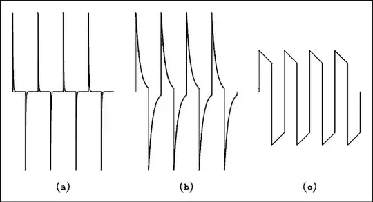
Module Contains a DC motor, and sensor output is analog. Internal schematic of module is like this:

enter image description here

image taken from here

I need to control the rpm of motor, but the module do not have such capability so i need to play with input voltage VCC to module. I've checked and it did work to control RPM. It can go down to near 0v, but the problem is with Tach pin's signal which have no sufficient voltage if module input voltage is near 0v. How i can overcome this?

I need an Intermediate circuit for this, and cannot use extra pin of UC like some answers below.

Thanks.
epsi1on
  • 103
  • 4
  • Is there any reason a resistive divider wouldn't work? – Yet Another Michael Jun 11 '21 at 06:24
  • I think yes, `Vreg` is adjustable (variable) and can go less than `5v`. Thus signal logic level will be less than `5v` and i think divider will not work. Also signal is analog – epsi1on Jun 11 '21 at 06:56
  • You seem to be mixing analog and digital. If so then you need to specify a switching threshold. The question is unclear. Can you draw a graph of output desired vs input voltage. Tip: 'V' for volt. 'k' for kilo. You've written '50 kelvin-hertz'. – Transistor Jun 11 '21 at 07:52
  • 1
    How will you deal with the case when Vreg is zero? – Andy aka Jun 11 '21 at 07:55

1 Answers1

2

It sounds as though you want to know the ratio of your analog sensor's output in relation to your supply voltage.

schematic

simulate this circuit – Schematic created using CircuitLab

Figure 1. Use a pair of 12:5 potential dividers to divide both the supply voltage and the analog sensor voltage by the same amount. Calculate the ratio in software.

Transistor
  • 168,990
  • 12
  • 186
  • 385