1

This is my first time asking a question in the forum and I hope that someone can help me on this issue. I am designing a board for 3 wheel robot using in my school with 2 yellow DC gear motors. It is powered from 2x18650 li-ion which is 8.4V when fully charged.

Here is the schematic of the pcb. pcb schematic

The problem I got is when running motor, the AMS1117 is getting very hot while it is not powering motors. The motors get power directly from VM trace which is from battery. It only powers esp32 module which should only be around 100mA.

Highly appreciate if any one can detect and share me the root cause. Thanks.

[Edit] The module to convert VM (battery) to 5V is this one 5V DC-DC Step-Down Power Module Here is my pcb layout enter image description here

[Update] Now I understood the root cause. As explained by @rdtsc, the AMS1117 is stressed due to the dropout voltage of the input voltage, it's dropped to below the mininum Vin required continously when motors start or reverse. Now I need to find a solution for the Vin. Thanks a lot for your helps.

Minh Ha
  • 11
  • 2
  • 1
    What actual current is the reg supplying? What voltage is dropped across the regulator itself? What power dissipation does that give you? What hoes the datasheet say about that dissipation, and any required heatsinking? how are you heatsinking it? –  Jun 09 '21 at 11:37
  • 1
    Is there a via almost connecting U3 pin 1 to pin 3? Does it output 3.3V as expected? Is any AC voltage measured on it's output (oscillating?) – rdtsc Jun 09 '21 at 12:35
  • @user_1818839 I don't know how to measure the actual current of the reg. It outputs 3.3V correctly. It's getting too hot to touch, even though I use a small heat sink for it. According to my calculation, the dissipation is (8.4V - 3.3V)*0.1A (in theory only, esp32 consumes around 100ma) = 0.51W, not much. If I don't run motor, everything is fine and it's not hot. – Minh Ha Jun 09 '21 at 13:52
  • @rdtsc it's not via, not's just pin 1 marker of the AMS1117. Yes, it outputs 3.3V correctly but will get very hot when running the motors. The diodes that protect from EMF also get too hot to touch. – Minh Ha Jun 09 '21 at 13:54
  • OK so 90C/W ... is its temperature consistent with a 45C temperature rise (e.g. 70C or so?) –  Jun 09 '21 at 14:35
  • @user_1818839 probably more, it hurts when touching. The thing that I'm confused is why it's only hot when running motors. The ams1117 doesn't power the motors. – Minh Ha Jun 09 '21 at 16:44
  • Measure AC volts across the 3.3v output. What is the reading, and does it change when motors are activated? – rdtsc Jun 09 '21 at 16:48
  • @rdtsc I measured both VIN and 3.3V, the AC volts are around 1.5-3V. Not sure if this is something abnormal or not. I tried desoldering the 8 LL4148 diodes used for protecting from EMF then the AMS1117 does not get too hot any more. I am still debugging if it's really due to them or pcb quality :(. – Minh Ha Jun 10 '21 at 07:52

2 Answers2

1

The AMS1117 is a linear regulator, designed to take in the DC battery voltage (say 12V) and output a regulated 3.3V, meaning that the 3.3V does not change (much) if the 12V changes (a lot.) Therefore, it is OK if Vin has an AC component (dips and spikes from motors starting and stopping, this is likely) but Vout should have almost no AC (since it is regulated and should prevent this.)

Normal Linear Regulator

The amount of this regulation-ability is called Line Regulation and Load Regulation in the above datasheet. This says that for normal operation, you should only see 0.025VAC or 25mVAC. Since failure to regulate a steady DC voltage creates an AC voltage "riding on top of" the DC voltage, this is why I asked to check AC volts. Seeing 1.5-3VAC on Vout seems to indicate that the AMS1117 is losing it's regulation-ability.

All linear regulators have limits as to how much current (I) and power (Vout x I) they can output, as well as how much power they themselves can dissipate ((Vin-Vout) x I). They also have limits on how much external input and output capacitance exist, and these values are not mentioned in this datasheet. This can be important, as too much capacitance can cause the regulator to lose regulation, essentially trying forever to correct Vout which is not changing fast enough due to too much capacitance. In other words, a regulator can become an oscillator if too much capacitance is added to it.

Linear Regulator Oscillating

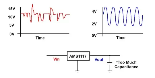
So the AMS1117 could be oscillating due to too much output capacitance. I'd suggest removing C10 and measure Vout AC volts again. If lower AC volts, then this was the problem.

Another thing to consider is the Dropout Voltage rating for this regulator. The datasheet says that up to 1.3V can be dropped across it before it starts to lose regulation. What this means is, when outputting 3.3VDC, if Vin drops below 3.3+1.3 = 4.6VDC, Vout will drop as well. If this is happening repeatedly (hundreds or thousands of times a second from motors turning on and off), it could stress the regulator, manifesting as extra heat.

The next step in troubleshooting such issues (oscillation, momentary dips in Vin, etc.) is to use an oscilloscope to determine exactly what these voltages are doing over time.

rdtsc
  • 15,913
  • 4
  • 30
  • 67
  • Excellent explanation. Thanks a lot for that. I used oscil to mesaure the Vin to the AMS1117 when running motors. it was dropped out from 7.4V to even 4.2V everytime when the motors reverse, and this is the cause that stresses the AMS1117 as per your explanation. Now I understood the root cause and need to find a solution for that. Any idea? May be a big alu capacitor like 220uF for the Vin? Thanks. – Minh Ha Jun 11 '21 at 07:31
  • Yes that should help; perhaps even more capacitance on C3, such as 1000µF/25v. Might have to experiment. A larger battery pack (same voltage) may also help, because it will likely have a lower internal resistance, and thus "sag" less. Or a different battery type (with lower internal resistance.) Motors + Micros can be tricky to pair together. – rdtsc Jun 11 '21 at 12:18
  • Yes, Motors & Micros is really a challenging project. Thanks for your great help. – Minh Ha Jun 14 '21 at 02:18
1

I think you have the wrong type of capacitor on the output of the regulator.

The AMS1117 datasheet says to use a 22 µF tantalum capacitor on the output of the regulator to guarantee stability.

Quote:

Stability

The circuit design used in the AMS1117 series requires the use of an output capacitor as part of the device frequency compensation.

The addition of a 22 μF solid tantalum on the output will ensure stability for all operating conditions.

When the adjustment terminal is bypassed with a capacitor to improve the ripple rejection, the requirement for an output capacitor increases. The value of 22μF tantalum covers all cases of bypassing the adjustment terminal. Without bypassing the adjustment terminal smaller capacitors can be used with equally good results.

To further improve stability and transient response of these devices larger values of output capacitor can be used.

The key thing here is "tantalum." Tanatalum capacitors have a certain amount of series resistance - it is inherent to the way they are made.

Ceramic capacitors have next to no series resistance.

That difference in series resistance often makes a large difference in stability. The AMS1117 was designed before high value ceramic capacitors were common (or even available.) It specifies a tantalum capacitor because that was the normal way to get a large value in a small space back when the AMS1117 was designed.

Your C11 appears to be a 0805 sized part:

enter image description here

That's going to be a ceramic capacitor to get the marked 22µF in that size.

The AMS1117 can easily start oscillating with a ceramic capacitor on its output.

JRE
  • 67,678
  • 8
  • 104
  • 179
  • Thanks for your advice. I replaced the C11 ceramic capacitor by tantalum, the oscillating of the Vout is much less. But the getting hot issue is still there. Anyay, I will switch to use tantalum as your advice because the output is better. – Minh Ha Jun 11 '21 at 07:33