I want to dim a 5A LED strip, so I am planning to create a PWM circuit, my primary MOSFET is the DMT3006 but since I am driving a fairly high current driving this MOSFET directly with my microcontroller would cause the MOSFET to heat up due to the high Rds on resistance, thus I am adding another MOSFET BSS138. The circuit looks like this:
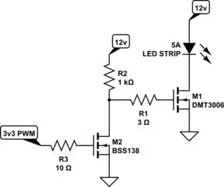
simulate this circuit – Schematic created using CircuitLab
Would you consider this circuit a good MOSFET PWM circuit? If not how can I improve it.
I would also like to know what are maximum frequencies I can go with the MOSFETs I have chosen, how do I compute them given the switching characteristics values in the datasheet. The BSS138 has the worst turn off delay of 36 ns of the two MOSFETs. So 27.77 MHz but I have to accomodate for an 8 bit duty cycle so 36 * 256 = about 109 kHz. So am I correct that the highest frequency I can PWM is 109 kHz?