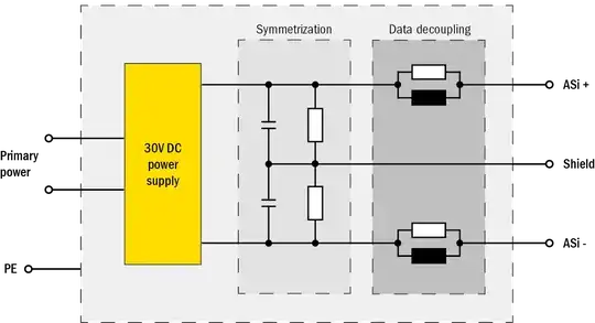
The resistors perform a weak pull from each side to ground. I don't know why they've labeled it as "shield" as AS-i cable doesn't have a shield. In the systems I'm familiar with the centre of the divider is connected to the machine frame / ground / earth. As you have pointed out the result of the resistors is that the lines are ±15 V with respect to ground.
The fact that there is a ground reference means that the AS-i gateway can monitor the + and - lines and detect a ground fault. I had to trace one in the past few weeks and we used a Fluke Scopemeter to monitor the lines relative to the machine frame and could see the two traces jump from ±15 V to 0 - -30 V intermittently. We eventually realised that the AS-i + wire inside a pad printer was being hit by the moving slide, the insulation had worn away and was making intermittent ground contact. This was easily fixed.

simulate this circuit – Schematic created using CircuitLab
Figure 1. Simple AS-i earth fault indicator.
To assist in future fault tracing we're building a simple tester as shown in Figure 1.
- Normal: both LEDs dim.
- Green: fault on AS-i-.
- Red: fault on AS-i+.
D3 and D4 provide reverse polarity protection. R1 and R2 are 1 W.
The hope is that thes can be clamped anywhere on the AS-i cable and the lights positioned for easy correlation between the indicators and the moving equipment.

