1

I am trying to simulate the resonance frequency of an antenna that can be modeled by a resistor in series with an inductor, both in parallel with a capacitor:

Antenna Equivalent circuit

By attaching the antenna to an AC current source and doing a frequench sweep, I want to:

  • Plot impedance vs frequency
  • Plot phase vs frequency

schematic

simulate this circuit – Schematic created using CircuitLab

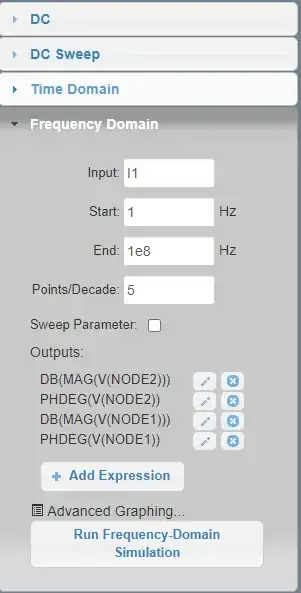
Using the frequency domain simulation:

enter image description here

I have plotted V vs frequency.

How do I now plot impedance vs frequency using CircuitLab?
enter image description here

ocrdu
  • 8,705
  • 21
  • 30
  • 42
Leo
  • 251
  • 1
  • 8

2 Answers2

2

How to plot it using Circuitlab, I do not know But I do know how to model it mathematically:

$$ \begin{alignat*}{1} \underline{\text{Z}}_{\space\text{in}}&=\frac{1}{\text{j}\omega\text{C}}\space{||}\space\left(\text{R}+\text{j}\omega\text{L}\right)\\ \\ &=\frac{\displaystyle\frac{1}{\text{j}\omega\text{C}}\cdot\left(\text{R}+\text{j}\omega\text{L}\right)}{\displaystyle\frac{1}{\text{j}\omega\text{C}}+\text{R}+\text{j}\omega\text{L}}\\ \\ &=\frac{\displaystyle\frac{\text{j}\omega\text{C}}{\text{j}\omega\text{C}}\cdot\left(\text{R}+\text{j}\omega\text{L}\right)}{\displaystyle\frac{\text{j}\omega\text{C}}{\text{j}\omega\text{C}}+\text{R}\text{j}\omega\text{C}+\text{j}\omega\text{L}\text{j}\omega\text{C}}\\ \\ &=\frac{\displaystyle\text{R}+\text{j}\omega\text{L}}{\displaystyle1+\text{R}\text{j}\omega\text{C}+\text{j}^2\omega^2\text{CL}}\\ \\ &=\frac{\displaystyle\text{R}+\text{j}\omega\text{L}}{\displaystyle1-\omega^2\text{CL}+\omega\text{CR}\text{j}}\\ \\ &=\frac{\displaystyle\text{R}+\text{j}\omega\text{L}}{\displaystyle1-\omega^2\text{CL}+\omega\text{CR}\text{j}}\cdot\frac{\displaystyle1-\omega^2\text{CL}-\omega\text{CR}\text{j}}{\displaystyle1-\omega^2\text{CL}-\omega\text{CR}\text{j}}\\ \\ &=\frac{\displaystyle\left(\text{R}+\text{j}\omega\text{L}\right)\left(1-\omega^2\text{CL}-\omega\text{CR}\text{j}\right)}{\displaystyle\left(1-\omega^2\text{CL}\right)^2+\left(\omega\text{CR}\right)^2} \end{alignat*}\tag1 $$

Where \$\alpha\space{||}\space\beta:=\frac{\alpha\beta}{\alpha+\beta}\$.

Jan Eerland
  • 7,203
  • 12
  • 21
  • Thanks, I've already used this model with python to get the graphs out. I was interested now in being able to use circuitlab to match with my simulaiton. – Leo Jun 04 '21 at 13:35
2

By attaching the antenna to a AC current source.....

and

I have plotted V vs Freq. How do i now plot Impedance vs Freq using Circuitlab?

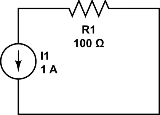
So, set the current source to be 1 amp RMS and the resulting plot of voltage is transferrable 1:1 to impedance.

Andy aka
  • 434,556
  • 28
  • 351
  • 777