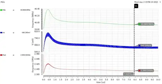
I built a verilogA model for every block used in PLL, I replaced a verilogA model for VCO with a designed one but, I got oscillations imposed on the control voltage as shown below.

Fdiv is the frequency of the signal at the output of divider
vc is the control voltage(changes within range of 20mV)
Fout is the frequency of the signal at the output of PLL
Thanks in advance