8

I'm building a lamp with twelve 3x700ma RGB LEDs in it, that need to be individually PWM controlled (100-200Hz), so they can display different colours from each LED. To do this then, I think I need a separate 700ma constant-current regulator circuit for each of the 36 individual LED chips in these RGB LEDs. (NOTE: I cannot put any of these LEDs in series, as each of the 3 chips in each of the 12 LEDs needs to be independently PWM controllable.)

Since this will all be enclosed in the lamp, I would like it to be at least 80% efficient, to reduce the amount of heat it generates. There is 90 watts of power flowing to those LEDs, so even at 80% efficiency, that still means 20w of heat from the constant current regulation alone.

I've investigated a bunch of options, but I'm wondering what other options there are that I've missed.

Option 1: Resistors

One options I looked at is using 3 switching dc-dc converters, adjustable, one for each colour of LED chip, and adjusting them to just above the highest Vfwd of the 12 LEDs, and using resistors to limit the current.

Pros:

  • If the Vsupply is only an average of 0.5V higher than the Vfwd of the LED, this ends up being about 80% efficient.

Cons:

  • This means measuring the exact Vfwd of each LED, and buying the correct value resistor for each one.
  • When the Vsupply is close to the Vfwd, small variations in the Vsupply can cause large variations in the amount of current flowing through the LED in that type of circuit.
  • I don't have a whole lot of room in the lamp, and 36 3-watt resistors take up a fair bit of space.

Option 2: NSI50350 - unsuitable

Datasheet: http://www.onsemi.com/pub/Collateral/NSI50350AS-D.PDF

When I first looked at this chip, I thought that it was exactly what I need. Two of them in parallel will regulate the current to 700ma. However, after getting a handful to try, it turns out I didn't read the datasheet closely enough. Unless I turn up the supply voltage to around 8 or 9V, it only allows less than 350ma (each) through. Running a 4.0 Vfwd LED on this at 8V generates an obscene amount of heat from the regulator, so it isn't practical for my project.

I know one solution to this would be to run multiple LEDs in series, however, due to packaging reasons, there is only room for 12 LEDs in this project, (One in each hole in one of these: http://www.flickr.com/photos/xenoc/7501865510/in/photostream) and each of those 12 LEDs needs to be PWM controlled indivdually.

Pros:

  • Easy to design and build circuit.

Cons:

  • Huge amount of heat.

Option 3: CAT4101

Datasheet: http://www.onsemi.com/pub/Collateral/CAT4101-D.PDF

I haven't tried these yet, but do I have a handful to try. From reading the datasheet, it looks like they should be able to operate with a supply voltage only 0.5V above the LED Vfwd.

Pros:

  • Low drop out, hopefully? Should mean not too much heat.

Cons:

  • ?

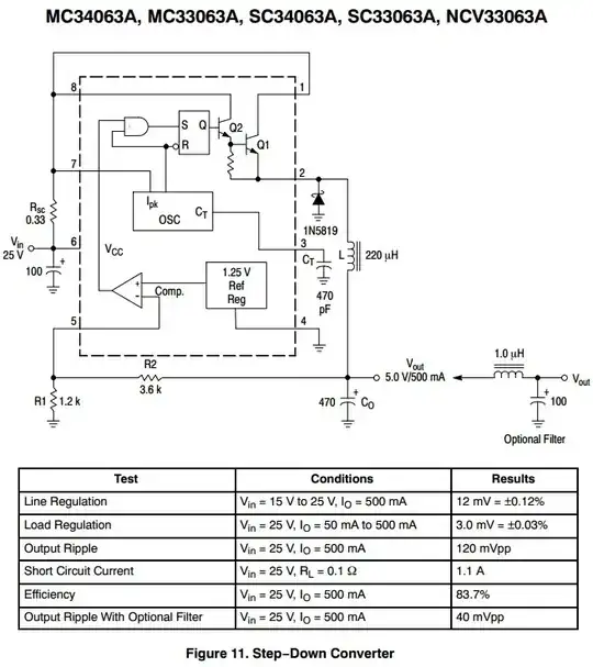
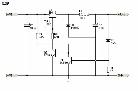
Option 4: switching regulator

I'm not very experienced in electronic design (I've only been doing this for a couple years, as a hobby) so I don't know much about switching regulators, other than that they are more efficient, but more complicated, than linear regulators.

I need to fit 36 of them into a fairly small area, I don't know how small they can be made. I've only recently begun soldering SMT parts, but I'll be having PCBs made for all of this, so I can go surface mount where needed, to keep things small.

Can switching regulators be PWM'd safely to dim LEDs?

Pros:

  • More efficient

Cons:

  • More complicated circuit. Not sure I'm experienced enough to diagnose any problems with it.

Option ??

What other options do I have? Any linear solutions need to have a low drop out voltage to avoid generating too much heat.

Further background

The basic idea of this is a lamp that would sit in my living room, probably being white most of the time (except when it's off), but that could flash a particular LED when something happens (like an email, or a tweet) or could be put into "party mode" where it would FFT an audio source (microphone or line-in) and use that to control the 12 LEDs. The actual PWM control will be done by a number of AVR chips, but that's a fairly independent part of the project.

Derek Lewis
  • 261
  • 3
  • 7
  • 1
    This is almost exactly a duplicate of [How can I efficiently drive an LED?](http://electronics.stackexchange.com/questions/55823/how-can-i-efficiently-drive-an-led/55824) – Phil Frost Feb 01 '13 at 21:01
  • That's a great post, thanks, I didn't find it when I searched before posting. There are some things about efficiently driving an high power LED that I'm still unclear on after reading it. 1. In the 2-transistor CCR, if 25% of the voltage must be across R2, that means at-best 75% efficiency, if I understand correctly? That will create too much heat for my application. 2. Can a switched-mode CCR be PWMed? If so, what PWM frequency is suitable for various switching frequencies? Should these be asked as separate questions? – Derek Lewis Feb 01 '13 at 21:32
  • you are right about the CCR efficiency. To make it more efficient, you'd need a supply voltage that is closer to the forward voltage of the LEDs. There are other linear current source designs that require less drop over the current sensing resistor, as well. SMPS frequencies vary, since different frequencies increase some efficiencies and decrease others. Higher frequencies allow smaller and more efficient inductors, but also increase switching losses. Anywhere between 1kHz and 10MHz can be expected. – Phil Frost Feb 01 '13 at 21:55
  • Can you give any examples (or links) of linear current source designs that do require less drop? Are there any that are better than the (advertised) 0.5V of the CAT4101 I mentioned above? I will research more about SPMSs in the meantime, thanks. – Derek Lewis Feb 01 '13 at 22:14
  • Just happened to encounter this, might be a good read: [Pulsed Over-Current Driving of Cree® XLamp® LEDs: Information and Cautions](http://www.cree.com/~/media/Files/Cree/LED%20Components%20and%20Modules/XLamp/XLamp%20Application%20Notes/XLampPulsedCurrent.pdf) – Phil Frost Feb 02 '13 at 13:49

2 Answers2

3

If somewhat more than minimum cost is acceptable you could implement a buck converter per LED. These could be very crude and low component count and not a vast price. Each converter would be able to set a current that was proportional to a PWM or analog input. Probably under $1 per channel.

Your 3 x Power supplies plus resistors idea is acceptable BUT can be improved in performance (with increased cost) by making it 3 x power supplies plus constant current sources. The constant current sources are not much different from the buck converters above but with no inductor.

Example. Imagine that your lowest Vf LED (probably red) has a Vf range of 2.0 to 2.5V.
You will need at least 2.5V supply plus headroom. Say 2.7 V.
Minimum efficincy will be when Vf = 2V = 2/2.7 = 74% BUT this is worst case Vf and in many cases the Vf range is lower.
eg say VF = 2.2 - 2.4. Vsupply = 2.6. Zmin = 2.2/2.6 = 85%. Boost supply to 2.8V for more headroom. Zmin = 2.2/2.8 = 78%
Again, this is worst case, so acceptable.

A buck converter will improve on the above.

One solution of zillions. Rsc not needed. Rather than sensing output voltage, LED current is sensed. This C had Vref = 1.25V = far too hight. It can be reduced to 0.6V effective using a diode but still too high. More modern ICs has a lower Vref OR a 1/4 IC section can be used per channel. PWM per channel then becomes 1 x SOIC MC34063 + 1/4 LM324 + a few resistors and a catch diode per channel. May be cheaper than more modern IC.

enter image description here


This circuit, from sound.westhost.com may be suitable.
I independently arrived at a similar version - works reasonably well. This is voltage feedback. Can be made current feedback. Vsense here = Vbe of Q1. This can be reducued with care.

enter image description here

Russell McMahon
  • 147,325
  • 18
  • 210
  • 386
  • Very interesting. Minimum cost isn't as important for this as efficiency, size and simplicity (in that order). After reading a bit about SPMS design, I wonder if an even simpler solution would work for me. Since I will be using a small AVR uC to PWM the LED , could that be used to drive a very minimal buck converter, just FET, inductor, diode, cap? Would I even need to feed back any control, or could I just use a hardcoded formula to determine duty cycle based on the desired brightness? – Derek Lewis Feb 03 '13 at 20:26
1

At these power levels, you will probably have to do some sort of switching to have a reasonable thermal design. It's not clear from your question if you need to control each of the 12 LEDs individually, or just the R G and B components. If you just need to control each color individually, a boost converter will allow you to put them all in series and drive a current through them even if your supply voltage is less than the total forward voltage of the LEDs. You'd need three supplies, one for each color.

If you need to control each of the 12 LEDs individually, making 12 switched mode supplies is probably not the most cost or space effective solution. You could, however, still PWM the LEDs individually. If you can select your supply voltage to be close to the forward voltage of the LEDs, then you can include a very small current limiting resistor, much smaller than you'd normally use. Sometimes, the resistance of the LED, MOSFET, and battery is sufficient.

You can then dim the LEDs by switching the full power supply voltage on them via PWM, as long as you don't exceed the maximum current of the LED with each pulse. While normally a small resistor won't provide adequate current regulation, you can include some active circuitry to limit the average current to stay within the thermal limits of the LED and compensate for thermal and manufacturing variation, as long as your resistor is sized to limit the peak current to within specifications.

Designing a switched-mode power supply is pretty complicated, so I'd suggest you do some more research and come back with specific questions when you encounter roadblocks if you take this path.

Phil Frost
  • 56,804
  • 17
  • 141
  • 262
  • Unfortunately, I do need to control all 36 LED chips (12xRGB) individually, so I think I actually need 36 switched mode supplies. Low cost is less of a goal for this project than efficiency and space constraints, so if a reasonable efficient SMPS can be built in those quantities for $5 each, that could be the best option. It's just my relative inexperience that's in the way of doing that. – Derek Lewis Feb 01 '13 at 22:03
  • Am I correct in my understanding that the CAT4101, while being linear, should be able to keep the efficiency above 80%? If Vfwd = 4.0V, and the input voltage is 4.5V to account for the 0.5V dropout, then the LED should consume 2.8W, and the CAT4101 should burn 0.35W, which means 88% of the power is being used by the LED. Across 36 LED chips, that totals 12W, which I believe will be managable. – Derek Lewis Feb 01 '13 at 22:11
  • @DerekLewis your calculations sound correct. That's the best case if the dropout is at 0.5V you will need a bit more to have a margin for regular operation. I was also thinking, you could get away with just one SMPS if you could short out the LEDs you don't want on with a MOSFET, but driving all those floating gates would be complicated. You could expect the SMPS efficiency to be about 90%, but it will be harder to design and not that much more efficient. – Phil Frost Feb 02 '13 at 12:46
  • @DerekLewis -- You might try [this one, using a PIC as a complete SMPS](https://romanblack.com/smps/pic-smps.htm) or the one at the bottom of [this page, the revised MikeMl SMPS driver](https://romanblack.com/smps/a05.htm). – MicroservicesOnDDD Sep 27 '20 at 00:33