1

I am planning to use RS-485 on a network and I do not have too much experience on the standard but I understand that termination resistance must be provided for considerable lengths and transmission speeds. For CAT5e the impedance matching value is typically 120 ohms. If the impedance varies depending on the cable length, then:

  1. Does the impedance matching resistor's value needs to be adjusted depending on the length of wire/speed of transmission, or can this be "activated" as a fixed value (120 ohms) whenever the length of cable increases or the user desires to increase the transmission speed?

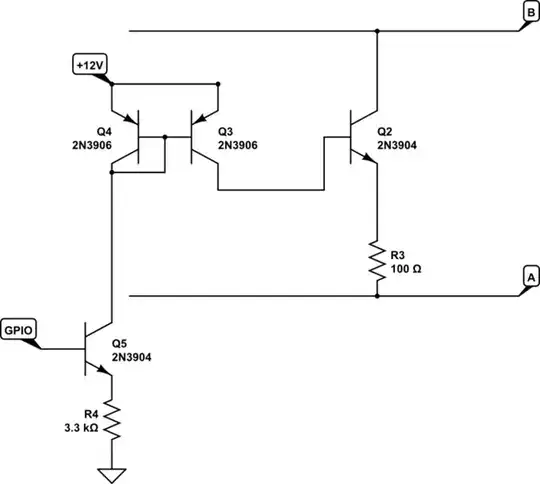
  2. Is it possible to provide electronic activation of the IM resistor using bipolar transistors? I have in mind something like this:

enter image description here

  1. As the activation of the transistor may depend on how the polarity is present at the A/B lines of the RS-485, I figure it could be possible to activate a set of resistors via transistors managed by a microcontroller GPIO. Is this correct? if not, can you share a specific circuit arrangement for this?

If the resistance needs to be controlled dynamically (i.e. depending on length, wire type CAT5e = 120 ohms and CAT6 typically 100 ohms) then depending on a command, I figure I can program the 100 ohm IM resistor set or the 120 ohm set if I can use a controllable termination.

I am planning on using MAX3081 with low bias for communications. The recommendation on their diagrams is to use terminators across A/B lines, not from signal to ground (in case someone asks).

enter image description here

Let me know your thoughts/recommendations on this.

Ed Zamper
  • 11
  • 3
  • 1
    Is your question how to design a product that can be used with either CAT5e or CAT6? – ErikR May 24 '21 at 22:09
  • @jsotola Yes I changed the schematic to force the signal through the resistor – Ed Zamper May 24 '21 at 23:10
  • Basicallly yes @ErikR. How to be able to implement electronic terminator R switching depending on the type of cable. – Ed Zamper May 24 '21 at 23:11
  • For CAT5e and CAT6 I would just split the difference and use 110R. If the cable impedances were vastly different perhaps provide a physical configuration switch or jumper? – ErikR May 24 '21 at 23:14
  • Ok, researching the problem points to using analog or bus switches. See the last response in [this TI forum discussion](https://e2e.ti.com/support/switches-multiplexers-group/switches-multiplexers/f/switches-multiplexers-forum/950198/ts5a3166-q1-rs485-termination-using-analog-switch) – ErikR May 24 '21 at 23:39
  • And here is an EXAR app note about using an AQY282S to do the job: https://www.maxlinear.com/appnote/an212_rs485-termination-resistor-switch-solution_080911.pdf – ErikR May 24 '21 at 23:43

2 Answers2

1

The impedance should not vary with the length of the cable. It is a combination of the cable inductance with its capacitance:

enter image description here From this article.

See also excellent answers here.

There are ICs with "Activatable" termination (such as LTM2881) but that is for connections that are not point to point.

enter image description here

Your proposed "solution" would just try to short the RS-485 lines to ground directly, not provide a controlled termination. And the 120R resistors are always connected. Also note that "A" is not Tx and "B" is not Rx. "B" is just "A" inverted.

enter image description here

Wesley Lee
  • 7,844
  • 6
  • 35
  • 53
  • OK you are right on the schema. I edited to show a different schematic that forces use of the resistor, though I suspect it wont' work either. What solution do you propose? – Ed Zamper May 24 '21 at 23:08
  • @EdZamper - What distances are you working with? MAX3081 isn't terribly fast so unless you are trying to solve a very specific problem I'd just use either 100R or 120R (or anything in between). Get some of the cable you want to work with (at the lengths you need), try the different termination values and check them on the scope. Lengths wont change the impedance but will change the effect of reflections. – Wesley Lee May 24 '21 at 23:34
  • It is a group of controllers for which the user can set up the ranges as needed. from 50 mts to 1200 metres. I got a 250 ft CATe5, bridged one side and inject current @5VDC. gave me 40 ohms, so I'm not sure of the calculations, I saw the document you shared and seems that is not the correct way to measure the impedance. I am a bit concerned about your statement that length does not increase impedance. With length the amount of copper increases and resistance on the porous atomic material should increase, but the diagram states otherwise. – Ed Zamper May 25 '21 at 00:11
  • @EdZamper - Impedance is not DC resistance.. – Wesley Lee May 25 '21 at 00:21
  • But it is.... it is the opposition to the flow of charge, but without considering capacitance and inductance effects. That's why it is also measured in ohms. – Ed Zamper May 25 '21 at 00:26
  • 2
    Characterisitc impedance is resistance to signals, not to DC current, it's measured in ohms. "capacitance and inductance effects" can also be computed in ohms but the result is a complex number, and is often frequency dependant. With transmission lines however the result tends to be mostly real and not highly frequency dependant. https://en.wikipedia.org/wiki/Characteristic_impedance – Jasen Слава Україні May 25 '21 at 03:00
0

the tricky part with your updated schematic would be getting the voltage on GPIO1 and GPIO2 to a voltage somewhere between A+0.6V and B+0.6V the absolute bus voltages in RS485 are poorly constrained. (could be anywhere +/- 12V)

maybe something like this instead:

schematic

simulate this circuit – Schematic created using CircuitLab

this uses a current source based on the GPIO voltage, Q5 and R4 to feed a current mirror Q3 Q4 which sends the current to bias the termination transistor on.

Only one transistor is used exploiting inverted beta.

If you don't have a 12V supply handy, perhaps use an optocoupler instead.

  • Mmh... this circuit looks sleek, thanks!. I was already thinking on using a couple of these analog switches https://datasheets.maximintegrated.com/en/ds/MAX14759-MAX14763.pdf which should be more stable in the long run. – Ed Zamper May 26 '21 at 03:03
  • Maxim makes good parts, but also has a reputation for discontinuing them if they don't sell enough. $3.19 at DK it might be cheaper to use a reed relay, or a small MOS based SSR like Panasonic AQY282SX (but they have a higher supply current) – Jasen Слава Україні May 26 '21 at 04:15