3

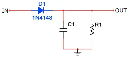
I am taking some off the shelf weighing scales and would like to interface a PIC to them for display and wireless transfer... The scales have four 3-wire load cells, one in each corner, and look very like the ones on the SparkFun web site. I am guessing but I think the load cells have two resistors in them, one for tension and one for compression. After the bridge arrangement the output of the bridge goes into a capacitor, resistor arrangement. I am guessing that the next stage is an amplifier of some type but it's inaccessible to me as it's a custom controller covered by a black blob.

sketch of schematic

Please can someone confirm the picture is about right and also suggest a good, PIC friendly way, to amplify the output either before or after the discrete.

Chetan Bhargava
  • 4,612
  • 5
  • 27
  • 40
  • The load cells seem to be pairs of 1k resistors. Looks like if the plate is compressed the Red wire values will go down and the Blue wire values will go up (or v.v) and the bridge changes to produce a difference signal. – NivagSwerdna Jan 31 '13 at 00:04

2 Answers2

1

You can use an instrumentation amplifier such as the INA114. If you have only a positive supply voltage, then you would want a rail-rail single supply inamp instead, an INA333 could work. The instrumentation amplifer amplifies the difference between the two inputs and adds a reference voltage to it. Since your ADC can only handle positive voltages, but your bridge may well return a negative value, you should use a, 2.5 volt reference input. This acts as a level shifter, and lets you send the signal straight into your PIC. You should calculate gain to make sure you use as much of your ADC range as possible.

Chintalagiri Shashank
  • 2,241
  • 17
  • 26
  • +1. Added INA114 datasheet link. Could not locate INA3333 datasheet, could you add that perhaps? – Anindo Ghosh Jan 31 '13 at 05:38
  • One subtle design feature of the existing scale that I would like to keep is that it does not need any other mechanism to turn it on; literally you get on the scale and the processor wakes up and displays a reading. For this to happen the bridge needs to be continuously active? Any ideas how that could be achieved? Having a voltage regulator continuously supplying say 5v to the bridge sounds expensive in battery life? – NivagSwerdna Jan 31 '13 at 23:46
  • You would need the bridge to be continuously active unless you introduce some other mechanism. A pressure sensitive switch connected to a wake up interrupt or so, perhaps. You could try reducing the excitation voltage and increasing the gain - the main loss you will have is in precision. The output can then be sent through a comparator which triggers a wake up interrupt. This is going to be more complicated, though, and may not work at all. At any rate, you cant reduce the excitation voltage by too much which means you will still bleed power. You can also leave the bridge off between readings – Chintalagiri Shashank Feb 01 '13 at 05:25
  • The existing scale does achieve this with just the circuit shown above and all powered from a single CR3032 battery. I will have to investigate further... – NivagSwerdna Feb 01 '13 at 08:23
1

The picture looks right to me. Each strain gage is comprised of two resistance grids. 1k is a common value for a strain gage resistance.

You should amplify this with an instrumentation amp, such as AD623 or INA333.

I'm assuming you don't have the mechanical design specs of the scale, so start with a gain of about 200 and see if that gives you the right span.

Anindo Ghosh
  • 50,188
  • 8
  • 103
  • 200
markrages
  • 19,905
  • 7
  • 59
  • 96
  • Thanks for the info. I looked again at the discretes on the output and I think I misread the SMD markings I think they are 881 and 683 being 880 ohm and 68k ohm. Not sure if that implies gain of 77 or not. – NivagSwerdna Jan 31 '13 at 17:53
  • I looked at a datasheet on SparkFun (similar looking component) and it states 50kg and 1mV/V. With equal loading 4 load cells would then have a 200kg capacity which seems to be about right for my (bathroom) scales. The chips you suggest look good but I'm still unsure about a couple of things; specifically I guess I need to drive the circuit (excitation) at a known (and fixed) either voltage or current... how would I do that? With a voltage reference? I would need both the excitation and the gain to remain pretty constant otherwise I would not be able to make consistent readings? TIA – NivagSwerdna Jan 31 '13 at 18:00
  • Excite the circuit with the same voltage you use as reference for your ADC. This keeps the measurement ratiometric and the exact voltage doesn't matter. The easiest way to accolmplish this is to use the supply you power the PIC with for both purposes, excitation and ADC reference. – markrages Jan 31 '13 at 18:25