1

MIDI Out Circuit MIDI In Circuit

I'm trying to make a MIDI Out circuit from the Sparkfun web page (https://learn.sparkfun.com/tutorials/midi-tutorial/all). My MicroController is a 3v3 device but I'm using two Not Gates as used in the sparkfun circuit, which are powered by a 5V rail.

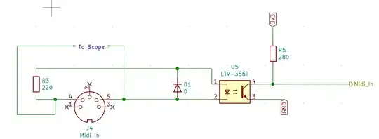
Because I'm having difficulty with the generated output I created a MIDI input circuit to measure the voltages in an Oscilloscope. I'm not actually powering the MIDI input circuit I'm just using the standard input resistance, 220 Ohms, a diode and Optocoupler so that I can measure what's happening.

So that's my two circuits, my problem is that my MIDI Output circuit is not being recognised by either of my synths. I decided that I must be transmitting the wrong signal, hence my test MIDI Input circuit to measure voltages.

So for comparison I plugged a MIDI Controller Keyboard into my MIDI Input circuit and measured the resulting voltages, when I pressed a key. As a second example I used a Sequencer with a MIDI Output and send a Note On message to my MIDI Input circuit and measure that on the scope. Finally I tried the SparcFun circuit with two Not gates which I'd created. All three look exactly the same to me, well there are differences in the third byte, the attack parameter of the note on message.

So the tree waveforms I'm getting MIDI Controller, MIDI Sequencer and My MIDI Output based on SparcFun circuit:

MIDI Controller Output

Sequencer Output

My MIDI Output Circuit based on SparcFun

So looking at those three outputs I'm struggling to understand why my output isn't being accepted or recognised by my MIDI Devices. The only thing I can think is that I'm not pushing enough current, but I'm powering my circuit off a bench top power supply pushing 9Volts into a 7805 Linear 5V which is creating the 5V Rail. In all cases the voltage is measured across the 220Ohm resistor in series with the input of an Optocoupler, so the Voltage drop across the input Optocoupler should be the same in three cases so the current through the 220 Ohm resistor should be the same in all three cases.

Be very grateful for any assistance or pointers, as to what's going on.
jwhitmore
  • 389
  • 1
  • 3
  • 9
  • 1
    Isn't the voltage on the yellow trace going negative? – Scott Seidman May 19 '21 at 19:29
  • I am puzzled. Based on scope trace, it should work. Unless you made some error and shorted signals with the ground clip, instead of measuring differentially. However, based on the chip being 74AHC1G04, it should not work as per the specs 3.3V data input is not guaranteed to be high enough, but it still looks like it should work based on the scope trace. – Justme May 19 '21 at 20:11
  • With a 3.3 V input signal, you are running the inverter outside its specifications. (But this does not make the output wrong, you just get greatly increased power consumption.) You must use a device with TTL-compatible inputs (AHCT). And you can replace the two inverters with a single buffer: 74AHCT1G125. – CL. May 20 '21 at 08:31
  • You input circuit, if you actually used it, would be wrong; see [4N35 opto-isolator for MIDI input does not work?](https://electronics.stackexchange.com/q/314150/29811) – CL. May 20 '21 at 08:32
  • Can you check the timing is exactly right? What do you mean with "not recognized"; what message are you sending, and what do you expect to happen? – CL. May 20 '21 at 08:37
  • By "not recognised" I mean that if I plug those three devices into a synth and send the three messages from the three different sources then in the first two cases the synth will play a note for the 'Note On' message. In the last case, even though the wave form looks the same, multiple synths are ignoring the message. MIDI Channel is set the same in all cases. Two produce a note. – jwhitmore May 20 '21 at 09:46
  • Just an aesthetic note, the bottom schematic is perfect (input on left, output on right, power on top, ground on bottom.) But the top schematic is opposite, breaking all of these conventions. I suggest redrawing the top schematic so it follows the same convention as the bottom schematic; even mirror the DIN connector or use both gender symbols if they are available (since one of these will physically be opposite.) Anything we can do to represent such details cleanly and in the standard form will only help understanding. – rdtsc May 20 '21 at 11:54
  • Thank you all for comments. Have to admit I'm confused by this circuit given that the MIDI Output is potentially connected to +5V on both pins 4 & 5. I'm wondering could change tack and instead of using the two Not gates use a 5V compatible GPIO pin on the UC configured as an open drain. Have it connected to 5V via a pull up and drive to ground when you want current to flow driving the connected device. The UART peripheral might not be too happy with that configuration. – jwhitmore May 20 '21 at 18:29
  • It does not matter whether pin 5 goes to +5V or open drain; in neither case does current flow. – CL. May 23 '21 at 15:15
  • The timing of the first waveform appears to be different. Which device is it? – CL. May 23 '21 at 15:15

0 Answers0