1

I am pretty new to designing amplifiers, but I have been playing with LTSpice and came up with a schematic, however I am not sure how to reduce the THD of the circuit. For 1kHz, I get the following from SPICE

Fourier components of V(out)
DC component:-0.000101871

Harmonic    Frequency    Fourier    Normalized   Phase      Normalized
 Number       [Hz]      Component    Component  [degree]    Phase [deg]
    1        1.000e+3    2.324e+0    1.000e+0    -179.11°       0.00°
    2        2.000e+3    1.038e-2    4.466e-3      94.08°     273.19°
    3        3.000e+3    4.972e-2    2.139e-2      15.96°     195.07°
    4        4.000e+3    1.017e-3    4.373e-4    -130.22°      48.89°
    5        5.000e+3    1.840e-3    7.914e-4      50.93°     230.04°
    6        6.000e+3    1.001e-3    4.304e-4     174.94°     354.05°
    7        7.000e+3    4.204e-4    1.808e-4      53.16°     232.27°
    8        8.000e+3    6.834e-4    2.940e-4    -168.34°      10.78°
    9        9.000e+3    4.017e-3    1.728e-3      80.26°     259.38°
Total Harmonic Distortion: 2.194679%(2.214350%)

Could you provide me with some pointers on how to improve this? Thank you!
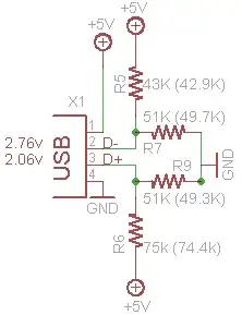
circuit

  • several hints. It's almost entirely 3rd harmonic, which is symmetrical. Plot this against drive level, you may find it improves rapidly with decrease in amplitude, which you haven't specified. You may find it's more acceptable with only a slight reduction in level. To reduce distortion you can a) increase loop gain and b) decrease open-loop non-linearity. The first is often easier, but you need to manage stability. – Neil_UK May 18 '21 at 16:20
  • 1
    Douglas Self wrote a lot about reducing distortion in this type of amplifier. Although I believe he always used a differential pair input. If you search for the writings of Douglas Self you may find some good tips. And using a differential input would probably be a good idea unless you have a good reason not to. – user57037 May 18 '21 at 18:03
  • What happens if you change the transient command to its full form, ie. `.tran 0 100m 0 0.1u` ? – Bruce Abbott May 18 '21 at 20:42

2 Answers2

4

I duplicated your simulation in LTspice IV and got similar results (2.2% THD). However the simulation ran suspiciously quickly suggesting that the Tstep value of 0.1 μs was not being honored, causing the waveform to be interpolated over longer periods that could cause artificial distortion.

LTspice has this to say about Tstep:-

Tstep is the plotting increment for the waveforms but is also used as an initial step-size guess. LTspice uses waveform compression, so this parameter is of little value and can be omitted or set to zero.

So I changed the transient command to .tran 0 100m 0 0.1u, which forces LTspice to use a maximum timestep (dTmax) of 0.1 μs. The 3rd harmonic then became much smaller and THD dropped to 0.502%.

The first (buffer) stage is not in the negative feedback loop, so I was curious to know what contribution it was making to THD. I measured distortion at the junction of C1 and R8 and the result was 0.503%, suggesting that all the distortion was being produced in the first stage! However if the following stage (Q2,R4) was disconnected then distortion at this point dropped to 0.04%.

From this I concluded that the buffer was not strong enough to maintain a pure voltage waveform when driving the smaller input impedance of the following stage. So I changed R16 from 6k to 1k, and THD at the amplifier output dropped to 0.057%, almost an order of magnitude less than with R16 = 6k.

Conclusions:-

  1. Do not trust LTspice to produce accurate waveforms without specifying a small maximum timestep.

  2. Distortion may be coming from places that you didn't think would be a problem.

Bruce Abbott
  • 55,540
  • 1
  • 47
  • 89
  • 2
    Compression can be annoying when measuring distortion. You can turn it off with a command, and also increase the calculation accuracy: `.OPTIONS plotwinsize=0 numdgt=7` – pipe May 19 '21 at 22:45
  • Thanks for that tip. Unfortunately it didn't make any difference to my simulation (perhaps it works better in later versions of LTspice, but I can't run them in Windows XP). – Bruce Abbott May 19 '21 at 22:59
  • oh awesome! Thank you so much! – Boris_bulletdodger May 20 '21 at 21:59
2
  1. Confirm DC signal is not clipping

  2. Balance Bias for Vce= (Vcc-2V)/2

  3. Increase DC gain with more stages

  • Your circuit has only 1 stage of voltage gain (Q2) divided by the R ratio feedback gain , this excess gain is the feedback towards nulling the quadratic non-linearity of Ic vs Vbe. It’s not enough but could be a lot better at lower input signals and balanced DC levels.

(R4/(R5//R8) is 10 but excess gain is only ~5 from open loop.

Thus instead of a 1 stage voltage gain and a lossy front end 100k loaded down by Req~15k, design an open loop gain >1000 or 10k or 100k (or use any OPAmp) then your excess gain can reduce your THD proportional to the excess gain which is reduced by your Miller cap added and necessary for multistage phase margin to linearize the higher order effects to 1st order at unity gain.

  1. But since your 3rd harmonic is greater than your 2nd which is the normal response, it suggests you are clipping the signal.

Consider any design efficacy and performance from its total power gain or in other words its voltage gain squared / Impedance gain from Zout to Zin as a product before defining your goals.

  1. Always keep Vce>1V at low current and Vce>2V at max current and don’t starve the bias current, otherwise it clips Vce=max. Voltage gain always increases with bias current due to the impedance ratio of Rc/(re+Re) and supply headroom when the bias is centred and operating in the linear region.

  2. A quick review of simple op-amp (OA) internal schematics shows how it’s done. enter image description here enter image description here enter image description here

Here's a simple way to boost current and stay linear with high gain.

  1. using high gain OA to drive complementary power FET's to null THD.
  • Red LED at 1.3V barely biases 1.2V FET's using less than 500 uA quiescent with CMOS OA. Different Vgs(th) values require different bias and there are thermal drift issues. But conceptually simply to drive 2 Ohms with a snubber cap for stability. enter image description here
  1. How to get a single H bias stage with Av=33 and THD ~ 0.23% on a large signal by neg. FB and careful R ratio biasing

The purpose of these exercises is to appreciate and simplify the effort in choosing components.

Tony Stewart EE75
  • 1
  • 3
  • 54
  • 182
  • Tony's last two paragraphs give good advice. Perhaps you're not constrained to keep amplifier's quiescent DC current LOW as op-amp designers are. So take advantage by scaling up some of those current sources/sinks. – glen_geek May 18 '21 at 18:33