A continuation of this project, that I hoped would be done and working by now.
The problem this time appears to be that the circuit is too slow. The desaturation/grayscale and attenuation seem to work as expected, but the picture is blurred to the right of where it's supposed to be by a few pixels, and looks about as I would expect from an exponential decay. So something clearly isn't fast enough.
(I haven't tried to invert the colors yet, since that involves a lot of coding, testing, debugging, etc. to get the timing right, so that it only inverts during the visible part and not the porches. I'd rather not do that until I get a clear non-inverted picture. Otherwise, the microcontroller is just a glorified shift register that produces DC control signals.)
Here's the current schematic:
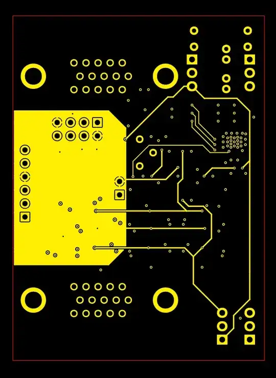
And the board:
And the datasheets:
OpAmp (U2,3)
Video Switch (U4)
Analog Switch (U1,5,6,7)
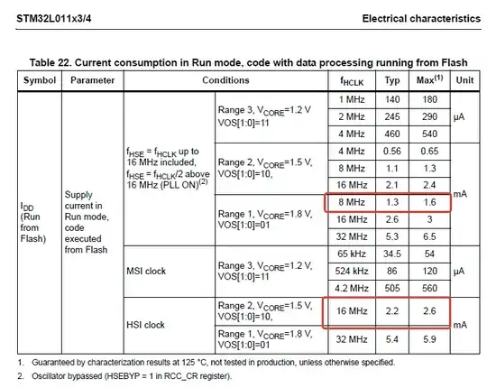
Microcontroller (U8)
I thought that everything had enough bandwidth for 1920 x 1080 x 60Hz (~62MHz), but I'm still getting the smearing.
Also, switching the LumMode signal (input to U1B towards the top left of the schematic) affects the output too, when the video switch (U4) is using that signal. Selecting pin 9 of U1B results in more smearing than pin 7 does. Am I dealing with some parasitic capacitance here?
Update:
In response to @JonathanS.'s comment on May 14, '21, here's a tentative solution. I would make it a comment, but I can't put the new schematic in it.
Changes:
- Reduced the desaturation resistors (R10,11,12,27,28,29,44,45,46) to give the grayscale buffer (U2D) only a small but present margin of output current in the theoretical worst case.
- Reduced the luminance mixing resistors (R1,2,3,5,6,7) to use most of the remaining margin of the input buffers (U2B,A,C), and balanced the two selections for roughly the same impedance looking upstream from the switch (U1B).
- Reduced the inversion resistors (R8,9,18,25,26,35,42,43,52) and increased the ballast resistors (R20,37,54) considering both the desaturation buffer's (U4A,B,C) and the inversion switch's (U1D,A,C) maximum current.
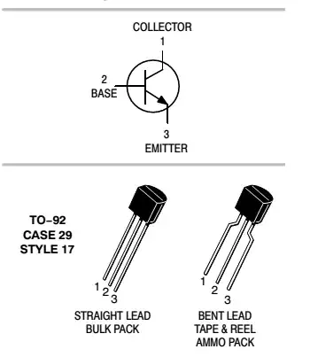
The desaturation buffer now sees 470R when not inverting, and ~41.5R when inverting, which is a bit lower than the 150R - 500R that it's meant for but still within the maximum output current of 50mA. - Reduced the sync pull-up resistors (R60,61), considering the NFETs' (Q1,2 - datasheet) saturation current at 3.3Vgs.
Originally intended for 5V sync's, but my 'scope measured 3.3V from an HDMI->VGA converter??? Anyway, it still works.
The silkscreen is of course updated for the new values, but it's not worth spinning another prototype board if these are the only changes - just swap out a bunch of 0603's on this one. Any other omissions?
