4

I have some questions regarding running an ATMEGA328P from a 3.7 V battery. These batteries can vary their voltage during discharge from 4.2 V to 3.0 V. So my questions are:

  1. If I power the ATMEGA328P directly from the battery, what would the voltage of the digital I/O pins be? Would it be the voltage at Vcc (i.e. the battery voltage)?
  2. If so, does that mean that the voltage used on a UART (TX, RX) line would be the battery voltage?
  3. How would I go about programming the device? I imagine selecting, for example, the Arduino Pro Mini at 3V3, 8 MHz within the Arduino IDE would not work (?), because Vcc is not 3.3 V but rather the battery voltage. Would I need to switch to a 3.3 V supply for programming?

Thanks in advance!
Dan Alvarez
  • 315
  • 1
  • 13
  • 1
    Does your barebone ATMEGA328P have Arduino bootloader preinstalled? Programming the chip from Arduino IDE would require it, I imagine. – Igor G May 14 '21 at 04:50
  • I'm still designing but I'd definitely install the Arduino bootloader. – Dan Alvarez May 14 '21 at 19:12
  • 1
    I suggest you clear that programming issue first! Your question makes me think that you're going to program the chip via UART, like Arduino boards - and that's not barebone. Bare ATMEGA chips are programmed via MOSI/MISO/SCK, see the datasheet for protocol description. Arduino boards can be programmed via UART because their ATMEGA controllers already have a small bootloader program preinstalled, which communicates with UART programmer. What I'm saying is that unless your bare chip has this bootloader program factory-installed you will have to use MOSI/MISO/SCK protocol to flash it. – Igor G May 14 '21 at 22:04
  • Yes, definitely. I will add an ICSP header to flash the bootloader to the microcontroller before programming it normally via UART. Thanks for the heads up, though. – Dan Alvarez May 27 '21 at 18:35

3 Answers3

4

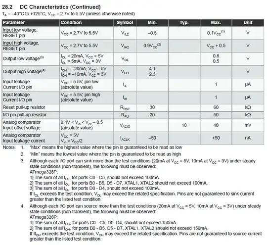
As usual, all this info is in the data sheet, but it can be hard to find for the inexperienced. In this case, it is Figure 28.2, DC Electrical Characteristics, and you need to find \$V_{OH}\$, the output high voltage.

enter image description here

Note that this is substantially lower than \$V_{CC}\$, and can vary under different conditions. It looks like assuming at least a diode drop is in order. If you need it to be \$V_{CC}\$ you should look to see if you can configure the ports to be open collector. Otherwise, the high output should be more than enough to be interpreted as a high for most logic families your devices are likely to be communicating with.

Your UART output will be at \$V_{OH}\$

Your last question is a little tougher

enter image description here

The absolute maximum voltage will be \$V_{CC} + 0.5\$. Sometimes, you can set things up so the PROGRAMMER provides the \$V_{CC}\$, and if you can do this, you won't have any trouble. If you can't do this, and you want to be sure your chip will function as specced, you'll need to somehow clamp the inputs if your programmer works at 5V. If your programmer works at 3.3V, you'll be fine, as anything above 0.6V on the digital inputs will be read as high.

Scott Seidman
  • 29,274
  • 4
  • 44
  • 109
3

Scott Seidman already addressed all your questions in detail, but since you mentioned a specific product (Arduino Pro Mini) using the uC, I'd like to make additional comments regarding the third question. Images below come from here.

As mentioned, disconnecting the board from the battery and powering it from the programmer itself (via USB) is really the easiest way:

enter image description here

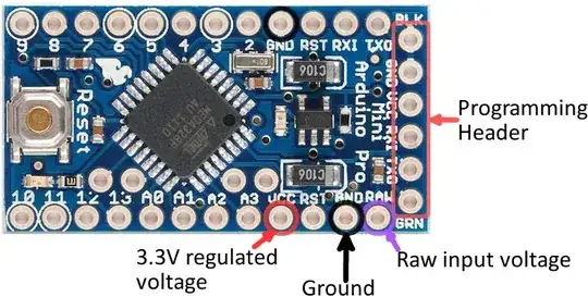
But if, for some reason, your programmer interface can't power the board, there is an integrated LDO regulator (as seen in the schematic). This means that you could connect the GND but not the VCC in the programming header, disconnect the battery, and power the circuit from the "raw" pin with voltages between 3.4 V and 12 V:

enter image description here

Since the board is available with regulators for 3.3 V or 5 V, this voltage should match the one used by your programmer.

devnull
  • 8,447
  • 2
  • 15
  • 38
2
  1. yes, battery voltage if the load is Hi-Z. If not the voltage will vary to about a diode drop below the Vcc.
  2. yes (these are digital uart lines, not RS232 or RS485 compliant, you still need a driver chip for that)
  3. 3V3 at 8Mhz will work. The main thing with the voltage to keep in mind, is that there is a max MHz speed that the CPU can do when powered by 3.3V and it can go faster when powered by 5V. Since you are using middle of the road voltages, choose 3.3V and you'll do fine.
Aaron
  • 7,274
  • 16
  • 30