0

My transistor is overheating when the MCU turns the fans on. How do I fix this?

schematic

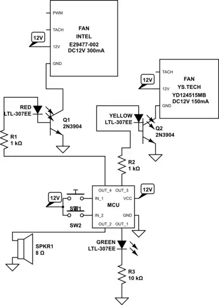
simulate this circuit – Schematic created using CircuitLab The MCU has an output of 12V.

  • (Immerse the circuit in an ice bath? That should keep it cooler. If worried, seal it up in a sandwich bag first.) More seriously, though, you haven't identified which transistor (and yes, I can see they are used similarly.) Plus, you haven't measured either collector voltage. You might start with some measurements for us, too. Finally, could you clean up the schematic a bit? It's a bit messy and I think you could spend just a little more time on your own question, rather than expect me to sit down and unscramble that thing to be sure I didn't miss something important. – jonk May 09 '21 at 00:04
  • Ditto what @jonk said, but also add the fan current. If you don't know it, measure that too. – John D May 09 '21 at 00:09
  • @user49279 Sure, slightly. But go [here](https://electronics.stackexchange.com/a/563683/38098) and read the Appendix there on how to redraw schematics. Right now it's just slightly less bunched-up. Which I cannot deny is slightly better. But not so much, really. And we need those measurements. – jonk May 09 '21 at 00:12
  • What is the output voltage from the MCU? Are you really connecting 12V inputs directly to it? – Elliot Alderson May 09 '21 at 00:23
  • I asked two questions and you only gave one answer. What is the output voltage from the "MCU"? – Elliot Alderson May 09 '21 at 00:26
  • Also, what is \$V_{CE}\$ for your transistors when the MCU output is high? – Elliot Alderson May 09 '21 at 00:27
  • Well, it should be about 0.5V. Can you provide a link to the manufacturer's datasheet for your transistors, and tell us what package they are in? Have you added any heatsinks? – Elliot Alderson May 09 '21 at 00:34
  • 1
    That transistor s not suitable for your application. Some MOSFET wil be better. – user263983 May 09 '21 at 01:32
  • 2
    You expect much from a 2N3904. – StainlessSteelRat May 09 '21 at 02:21
  • That’s correct, a PN2222A would barely do it with 50 ohm driver and 50 Ohm resistor from 5V. When I designed a variable speed fan for my rack to Lucent I used 48V fans with a transistor to modulate the Vadj on a power LM317 on a heatsink. So using a TO-92 2N3904 improperly with insufficient drive current will just burn up and I explained in my answers. – Tony Stewart EE75 May 09 '21 at 19:58

2 Answers2

2

Another simple way to look at this is just by resistance ratio and power ratio.

  • If you have a 3.6W load and only a TO-92 switch, what switch resistance and conditions are required to use this?

Consider Rja= 200'C/W lets consider 1/4W max for a 50'C junction temperature rise above ambient.

  • Loss/Load= 0.25/3.6W x100% = 7%

  • Load = 12V/0.3A= 40 ohms

  • Loss = 7% of 40 ohms = 2.8 Ohms

BLDC fans have a steady-state (SS) proportional current above stall speed so may be considered like a SS resistive load.

What switches are <= 2.8 Ohms at <= 300 mA ?

  • How do you choose ?

    • For NPN BJT's which are slightly better than PNP then you look on the datasheet for Vce/Ic at the current you intend to use. We call this $$R_{CE} =\dfrac{V_{CE}}{I_{C}}$$
    • Rce only appears on datasheets of "superbeta" transistors because in saturation Vcb is starting to forward bias and shunt the current gain, hFE towards about 10% of it's max hFE rating as practical limit. But you can compute this for any BJT. Why does hFE reduce when it saturates.
  • 2N3904 TO-92 ON SEMI fig2 : Rce= 0.12V @ 100mA Max @ hFE=10 ( BAD choice , not rated for 300 mA, only 200 mA and you should have heat margin so derate 50%)

  • PN2222A TO-92 can be made to work with Rce <=2 ohms but a power transistor or low RdsOn power FET is clearly a better choice

Tony Stewart EE75
  • 1
  • 3
  • 54
  • 182
0

To reach Vce(sat) rating and it’s rated switching current the typical device must use Ic/Ib=10 unless using a super beta type transistor.

For the 300mA fan that means 30mA. You didn’t state what your MCU p/n is and that is critical. That would be the absolute max current also for the typical 20mA LED

The 1k at best can only drive 1mA from 12V. Try stating the actual specs and consider some from 5V like 5-2.1V-0.7V=Vr=2.2V drop across resistor and that means 2.2V/30mA= 73 Ohms and if it is a 50mOhm CMOS driver that means adding only 23 Ohms , so either give MCU specs or try changing 1k to something between 23 and 100 Ohms.

When driven with low current the transistor is no longer in saturation and at Vce=6V the transistor will have risen to 50% of the power drawn by the fan. Meaning the 12V*300mA 3.6W fan will be drawing 150mA or 1.8W the same as the transistor probable only rated for 0.5W at 120’C (Too tired to look up) (200’C/W)

Tony Stewart EE75
  • 1
  • 3
  • 54
  • 182
  • Even transistor is saturated, TO-92 (typical for 2N3902) can not dissipate 900mW. Typical betta for that type of transistor around 100, so the case, you describing, is possible but not usual. – user263983 May 09 '21 at 01:29
  • @user263983 I said IF the fan was at 6V (say with 1mA in and hFE =150) and then the transistor would draw the same 1.8W but this one was only rated at 0.5W ... So my analysis is correct why it was overheating and how to correct that, but no idea what current without test results. Got it? – Tony Stewart EE75 May 09 '21 at 11:01
  • You described the case which possible but the possibility is low. Most important the transistors body can not dissipate the heat even it fully opened. Wrong choose of components. – user263983 May 09 '21 at 11:22
  • I didn't choose the components (-1) I described why it failed and what it would take to drive Vce(sat) (-1) and hFE=10 ... read again @user263983 -1 Most? No the std TO-92 is 200'C/W Rja – Tony Stewart EE75 May 09 '21 at 11:39