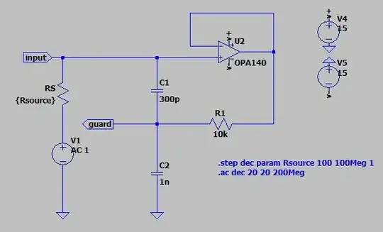
I am designing a guard drive for a coaxial cable, to drive its shield as a guard for low leakage measurements. After seeing some issues in the sim, I arrived at the following minimum circuit which reproduces the issue:
The lines from right to left show a source impedance variation from 100 ohm to 100 Mohm. The desired bandwidth is DC - 50kHz with a gain of ~0dB. The bandwidth can be lower for very large input impedance as they roll off sooner even with driven guard. But the amplification is a problem.
C1 is the inevitable capacitance between the signal and its guard. C2 is the inevitable capacitance between the guard and ground. These caps are inevitable because they represent what the cable and EMC caps/diodes would contribute. Individually, neither C1 nor C2 lead to oscillations when R1 is sufficient. However, when both are present, any value of R1 will lead to oscillations for some input impedances at some frequencies. I also tried more complex impedances instead of R1 but it didn't improve substantially.
So I am now puzzled. How are driven cable guards implemented in practise, to prevent oscillations?
EDIT:
The only remedy, I found so far is adding capacitance from the signal to ground (essentially adding to the Opamp input capacitance). However, in practise, adding ~1 nF of capacitance from signal to ground can also be a concerning source of leakage. And this also limits bandwidth, so I hope that there is a better solution.


