The first thing I do before attempting to analyze a circuit is to redraw that circuit. The process of just doing it helps me think and gather up a few details that I may not notice so easily, just staring at someone's depiction. But I can often help the readability, too, which improves understanding and reduces chances for mistakes, later.
It takes lots of practice to accumulate a good sense. But that practice is well worth the time. I'll add a "boilerplate" discussion at the bottom of this, about some guidance in getting started.
Also, keep in mind that you get to call one node "ground." If you select a really convenient one, it can greatly simplify the analysis and reduce changes for mistakes, as well. (This doesn't always have to be the obvious choice or the one that the writer chose. You can move it to a different location if that helps your analysis.)
Those things said, I see:
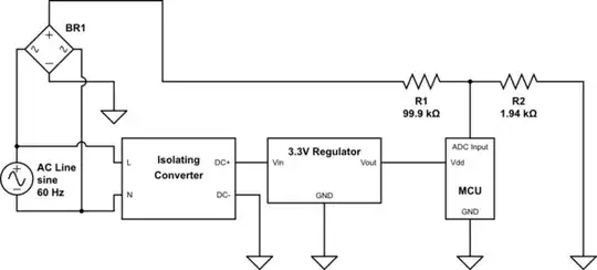
simulate this circuit – Schematic created using CircuitLab
I use a concept of outflowing and inflowing currents, which is how Spice programs develop their matrices as well, when developing my KCL equations. I place the first on the left side and the second on the right side. These, of course, must equal each other.
I present this as an alternative for you to consider. Traditional teaching tells you to make decisions about voltage differences across a component. But this is fraught with the getting the sign right every time. And too many people, too many times, get it wrong. Or, at least, don't get it consistently right. Even I don't get it consistently right and I've been doing it for decades. Please see the KCL Addendum below for further discussion.
The nodal equations are then:
$$\begin{align*}
\begin{array}{c}
{\text{TP}_3:}\vphantom{\frac{V_{\text{TP}_3}}{R_1}}\\\\
{\text{TP}_2:}\vphantom{\frac{V_{\text{TP}_3}}{R_1}}\\\\
{\text{TP}_4:}\vphantom{\frac{V_{\text{TP}_3}}{R_1}}
\end{array}
&&
\overbrace{
\begin{array}{r}
\frac{V_{\text{TP}_3}}{R_3} + \frac{V_{\text{TP}_3}}{R_4}\\\\
\frac{V_{\text{TP}_2}}{R_1} + \frac{V_{\text{TP}_2}}{R_4} + \frac{V_{\text{TP}_2}}{R_5}\\\\
\frac{V_{\text{TP}_4}}{R_2} + \frac{V_{\text{TP}_4}}{R_5}
\end{array}
}^{\text{outflowing currents}}
&
\begin{array}{c}
&\quad{=}\vphantom{\frac{V_{\text{TP}_3}}{R_1}}\\\\
&\quad{=}\vphantom{\frac{V_{\text{TP}_3}}{R_1}}\\\\
&\quad{=}\vphantom{\frac{V_{\text{TP}_3}}{R_1}}
\end{array}
&
\overbrace{
\begin{array}{l}
\frac{0\:\text{V}}{R_3} + \frac{V_{\text{TP}_2}}{R_4} + I_1\\\\
\frac{12\:\text{V}}{R_1} + \frac{V_{\text{TP}_3}}{R_4} + \frac{V_{\text{TP}_4}}{R_5}\\\\
\frac{0\:\text{V}}{R_2} + \frac{V_{\text{TP}_2}}{R_5}+I_2
\end{array}
}^{\text{inflowing currents}}
\end{align*}$$
Re-arranging them in order to detect your mistake:
$$\begin{align*}
\frac{V_{\text{TP}_3}-0\:\text{V}}{R_3} + \frac{V_{\text{TP}_3}-V_{\text{TP}_2}}{R_4}-I_1&= 0\:\text{A}\\\\
\frac{V_{\text{TP}_2}-12\:\text{V}}{R_1} + \frac{V_{\text{TP}_2}-V_{\text{TP}_3}}{R_4} + \frac{V_{\text{TP}_2}-V_{\text{TP}_4}}{R_5}&= 0\:\text{A}\\\\
\frac{V_{\text{TP}_4}-0\:\text{V}}{R_2} + \frac{V_{\text{TP}_4}-V_{\text{TP}_2}}{R_5}-I_2&= 0\:\text{A}
\end{align*}$$
(You may notice how much cleaner the outflowing/inflowing arrangement appears. It's easy to read and understand. Now compare it to the sign-ridden hot-mess once it is arranged in the more traditional fashion. The traditional approach just begs for sign errors to be made: no matter how good you get at it. Leave it behind as soon as you are allowed to do so and never come back to it.)
In any case, at this point I think you can readily find your own errors. Let me know, if you still need some help, though.
Redrawing Schematic Addendum
Rules to live by are:
- Arrange the schematic so that conventional current appears to flow from the top towards the bottom of the schematic sheet. I like to imagine this as a kind of curtain (if you prefer a more static concept) or waterfall (if you prefer a more dynamic concept) of charges moving from the top edge down to the bottom edge. This is a kind of flow of energy that doesn't do any useful work by itself, but provides the environment for useful work to get done.
- Arrange the schematic so that signals of interest flow from the left side of the schematic to the right side. Inputs will then generally be on the left, outputs generally will be on the right.
- Do not "bus" power around. In short, if a lead of a component goes to ground or some other voltage rail, do not use a wire to connect it to other component leads that also go to the same rail/ground. Instead, simply show a node name like "Vcc" and stop. Busing power around on a schematic is almost guaranteed to make the schematic less understandable, not more. (There are times when professionals need to communicate something unique about a voltage rail bus to other professionals. So there are exceptions at times to this rule. But when trying to understand a confusing schematic, the situation isn't that one and such an argument "by professionals, to professionals" still fails here. So just don't do it.) This one takes a moment to grasp fully. There is a strong tendency to want to show all of the wires that are involved in soldering up a circuit. Resist that tendency. The idea here is that wires needed to make a circuit can be distracting. And while they may be needed to make the circuit work, they do NOT help you understand the circuit. In fact, they do the exact opposite. So remove such wires and just show connections to the rails and stop.
- Try to organize the schematic around cohesion. It is almost always possible to "tease apart" a schematic so that there are
knots of components that are tightly connected, each to another, separated then by only a few wires going to other knots. If you can find these, emphasize them by isolating the knots and focusing on drawing each one in some meaningful way, first. Don't even think about the whole schematic. Just focus on getting each cohesive section "looking right" by itself. Then add in the spare wiring or few components separating these "natural divisions" in the schematic. This will often tend to almost magically find distinct functions that are easier to understand, which then "communicate" with each other via relatively easier to understand connections between them.
- You get to choose exactly one node and call it "ground." If the purpose of redrawing the schematic is for understanding it, then choose a node that helps achieve that. When signals are single-ended, they share a common node and you should select this common node as "ground." If the purpose is for analysis, then you can select this for the purpose of reducing the equation complexity. Often, this will mean the node that is "busiest" (has the most terminals attached to it.) Either way, make this choice wisely and it will help a great deal.
The above rules aren't hard and fast. But if you struggle to follow them, you'll find that it does help a lot.
You can read a snippet of my own education by those schematic draftsmen at Tektronix who trained me by reading here.
KCL Addendum
The KCL equations may appear to treat node voltages as if they don't have to be differences, but can be absolute values. However, that's not really the case here. In fact, I'm just using superposition (which is easily seen once you've really had the concepts deepened into you.) This is, in fact, the same technique used within Spice programs (those where I've directly looked over the code used to generate these.)
Perhaps the easiest way to imagine is that absolute voltage at a node spills away from that node through the available paths. But also that absolute voltages spill into that node from surrounding nodes through those same paths. So long as you treat them all as absolute values, the result is the application of a simple superposition concept that results in, effectively, the potential differences controlling the result.
You can test this, easily, by rearranging the resulting equation(s), moving the right side over to the left side and then combining terms. You'll then see the usual potential differences that you expect. So it really is the same result.
The reason I very much prefer this method is that it is simple to visualize and very difficult to make mistakes. You can easily orient yourself to a node and then work out the terms for out-flowing currents for the left side of the equation. Then all you have to do is position yourself at each surrounding node and work out the terms for in-flowing currents for the right side. It's almost impossible to screw that up.
Conversely, when you are instead struggling to work out the potential differences in your mind (using the more traditionally taught method) and just write those terms, you often find yourself not entirely sure if you have the sign right as you try and add them up, correctly. I find, time and time again that not only others wind up messing up somewhere and making an uncaught mistake.. but that I also make those mistakes, as well. Even with lots of experience, you just aren't 100% sure and you often find yourself double and triple checking your work, just in case.
That doesn't ever happen, once you start using the superposition method. It just works. It just works right. It just works right each and every time. I've never, not once, screwed up. (I make typos. But not sign errors.) It's too easy to use.
So voltage spills away from a node via available paths and voltage spills into a node from nearby nodes via the same available paths. The only caveat is that a current source or sink can only flow in, or flow out, but not both directions. It's one way. So it will either appear on the out-flowing side or on the in-flowing side -- but not both sides.
This also works perfectly well with capacitors and inductors. It does turn the equation into a differential/integral equation. But that's just a technicality. It's still correct.
 ?
?