You need to ask yourself "what is the purpose of the shield?"
In my mind, it serves 2 purposes. 1) Protection from external electromagnetic disturbances (ESD) and 2) Prevent internal EMI radiating out.
Note that an unconnected cable (a high impedance cable) will create electromagnetic fields and will act as a dipole antenna. It can be a very efficient radiator > 1MHz.
A loaded cable will create a loop currents (i.e. loop antenna) and generate magnetic fields. These can be highly effective radiators at low frequencies.
In both cases, the situation of concern is where the cable length is > 1/20th the wavelength of concern. So a cable is of concern whether it is loaded or unloaded, it's just different.
Personally I always keep the shield separated from DGND as I do not wish to provide a low impedance path for current to travel down my shields. (Currents will tend to the lowest impedance path). It is vital that your shields do not carry current. They should be tied to a "quiet" voltage potential. i.e. A they form part of your Faraday cage.
Also, due to skin effect, a shield will act like two conductors, on the inner and outer surface. You want that outer surface to be quiet, so it needs high impedance to your noise sources. (In my opinion).
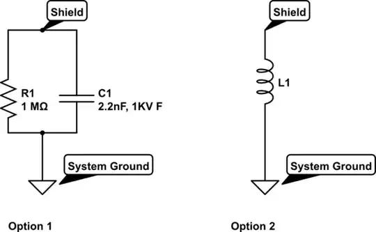
As a result, either of those options is acceptable, although the ferrite bead does not have to reference a ground in order to provide a high impedance path. The capacitor needs to be tied to a low impedance (quiet) GND point to be effective.
Personally, for ESD, I want to provide a path to EARTH for the fault current. I do not want to route this current to the DGND plane. As a result, you will often find that the shields are all connected to EARTH at some point in the system.
If the discharge path is via your DGND plane, then the capacitor is lower impedance and therefore more effective, with a 8kV strike being clamped to about 900V (4n7) for 10us with a peak of 30A current flow. The inductor will "clamp" to about 2.4kV for 100ns and the same peak current. So you get a shorter transient but higher transient with the bead. If you elect to parallel a 330R resistor with the capacitor, it will be subjected to up to 4A of current during the discharge event. All of which is to suggest it would be smart to use larger components and making sure your capacitor is "ESD rated".