1

I've built an array of Infra Red LEDs on a 4x4 grid. I want to get the most power out of these LEDs as I can, but I'm scared I might burn them out.

Right now, I'm using 2AA batteries (1.5V each), which is powering the array.

First of all, the starting volts is 3V right? When I measure the voltage at the other end, I get about 1.5V (There's about 6 feet of cable from the battery to the LEDs).

Even with this powering the array, they get very warm and smell a little. Is this too much voltage? Help me out here,

Here are the specs for the IR LEDs: http://www.rapidonline.com/pdf/58-0116.pdf

The array contains 16 IR LEDs, each require maximum of 5 Volts. So surely 80 Volts would be ideal? Then again, that doesn't sound right - and I don't know anything about electronics.

One more thing, I haven't used a resister at all within this array. I normally use one for a normal LED, but the IRs didn't light up at all with it, and works fine without one.

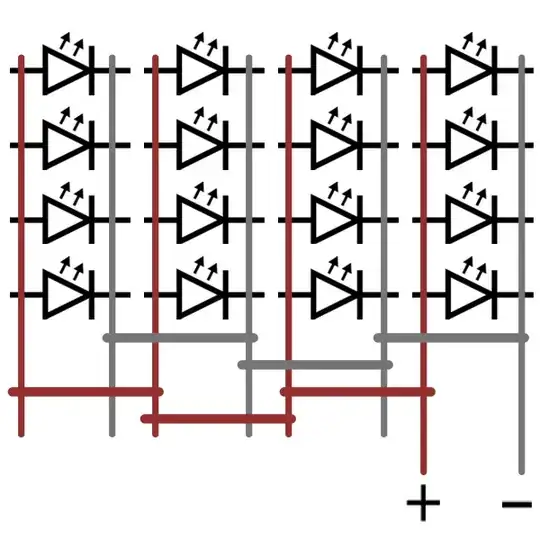
Here is a rough diagram showing you how I have it wired up: enter image description here

FYI: I'm hoping to hook this up to an Arduino at some point.

Nick Alexeev
  • 37,739
  • 17
  • 97
  • 230
Oliver Jones
  • 121
  • 1
  • 6
  • 1
    See [How can I most efficiently drive an LED?](http://electronics.stackexchange.com/questions/55823/how-can-i-most-efficiently-drive-an-led) – Phil Frost Jan 25 '13 at 21:33

4 Answers4

4

The only reason you have not vaporized your LEDs is because your AA batteries can't supply so much current. The "maximum 5V" you cite is the maximum reverse voltage these LEDs can before they break. Remember an LED is a diode which allows current in only one direction. 5V is the maximum voltage when you have them installed backwards

The forward voltage in the datasheet is 1.6V - 1.8V. This is, as you say, what you measured.

You should read How can I efficiently drive an LED? which covers most of this.

Phil Frost
  • 56,804
  • 17
  • 141
  • 262
2

You need a current-limiting resistor!

Your statement:

I normally use one for a normal LED, but the IRs didn't light up at all with it, and works fine without one.

Were you using an infrared camera to detect if the LED lit up? You're not going to be able to see whether it lights up or not... it's infrared!

Look for other questions about calculating the correct current-limiting resistor for the diode to operate at its \$I_f\$ (forward current) rating.

Edit:

The diagram showing one current limiting resistor for four parallel LED's would work, but could have problems.

Let's say your LED's require a \$V_f\$ of 1.6V and have a \$I_f\$ of 20mA. The voltage drop across the resistor after supplying 3V is 1.4V. Given that \$R = \frac{E}{I}\$, we know that the four LED's will require 80mA combined. Thus \$R = \frac{1.4}{0.08} = 17.5\$. So you use a 17.5 ohm resistor. Everything appears to work just fine.

Now imagine one of the LED's fails in a group of four. The voltage drop across the LED's is the same (1.6) but the current should now be limited to 60mA, not 80mA. The current-limiting resistor is no longer the appropriate value to limit current to 60mA at it's 1.4V. If three out of four LED's were to fail or be removed, you'd now have 80mA available for one LED, which for this example of a diode expecting \$I_f\$ of 20mA is likely too much.

This is just an example of how things could fail. It's very likely that the circuit, as described, would work for a long time. If I were designing this to be a commercial product, I would change it.

JYelton
  • 32,302
  • 33
  • 134
  • 249
  • Thanks, I am using an Infra Red camera - yes (it also has small a visible light red glow). Will I need to use one resistor? or one for each LED? – Oliver Jones Jan 25 '13 at 21:38
  • If you have control over how the LED's are wired, I would change them to have as many LED's connected in series as are practical for your voltage source. With 3V, that's only one LED, because two would require 3.2 volts. Each series-connected batch should get its own current-limiting resistor. If you can only supply 3V, then you'll need a resistor for every LED. The reason is that LED's in parallel are not current-limited individually, and various factors can cause some to get more current than others, and you get a runaway condition. – JYelton Jan 25 '13 at 22:40
  • Okay - would this work? olliejones.com/LED_setup_resist.png - I'm not sure what size resister to use though. – Oliver Jones Jan 25 '13 at 22:52
  • You've got four LED's in parallel with one current limiting resistor. It's not ideal, but since you're using batteries as a source, it's probably OK. The issue is mainly if you have one LED that, for whatever reason, starts to differ from the others, you get varying currents *after* the current limiting resistor which can cause problems. Imagine if one LED was removed (failed, whatever). I'll update the answer accordingly. – JYelton Jan 25 '13 at 23:25
  • Thanks @JYelton - is 17.5 ohms of resistance really worth it - it seems so minimal? How long do you reckon this circuit would last for without these resistors? – Oliver Jones Jan 25 '13 at 23:44
  • 17.5 ohms is a lot more than the copper you'd have otherwise. Grab a breadboard, and some visible light LED's. Omit the resistor and things will work. For a while. How long before it fails? That's a question of LED quality, environment, temperature, humidity, power source stability and quality, and a host of other variables. It's hard to say how long it would last: could be hours, weeks, or years! – JYelton Jan 26 '13 at 00:39
  • I don't think using a single resistor for 4 parallel LEDs is a great idea. Its fine to use a single resistor for series LEDs, but not for parallel ones. The forward voltage of the LED is specified as 1.6 typical and 1.8 max, which means they aren't particularly precise. You could have one LED of the 4 with 1.6V, and the other three with 1.7. The voltage across each of the LEDs is then restricted by the lowest forward voltage in the bank, and _All_ the current you've budgeted goes though that one led. For a demonstration of this effect, take a red and green LED in parallel and see what happens. – Chintalagiri Shashank Jan 26 '13 at 05:33
1

This setup of LEDs is parallel so your forward voltage of the LED is 1.6V. Do not use 80V! You have to use a limiting resistor so that your per LED current doesn't exceed 80ma. Total current of the array would be 1280ma. Remember 100ma / LED is absolute maximum according to the datasheet!.

Chetan Bhargava
  • 4,612
  • 5
  • 27
  • 40
0

If you look at the datasheet, you'll see a spec called the 'DC forward voltage'. This is the voltage that the LED needs to operate, and the voltage across the LED will always be either zero, negative (upto -5V, where it reaches reverse breakdown), upto 1.6 volts, where is isn't conducting, or 1.6 volts, which is the only condition where the LED is actually operating and emitting light. This derives directly from the standard characteristics of any Diode, the LED being an example of it. Whatever voltage you apply across a diode greater than the diode forward voltage, the diode will act as a short circuit between the voltage at the diodes anode and the (cathode+forward voltage). As per ohms law, this means an infinite current can flow through the diode (in first approximation kind of theory). The resistor which you use in series normally allows an LED to function by causing the voltage to drop from the source voltage (3 volts in your case) to the required (1.6V). In doing so, it also sets the current through the LED as per ohms law, ie, I = (3.0-1.6)/R.

By not having a resistor,your circuit is producing the necessary voltage drop using the resistance it has available to it, ie, the resistance of the wire and the internal resistance of the battery. This means 2 things. First, this is unhealthy for the battery, and the battery will heat up due to joule dissipation. Secondly, the current through the LED is higher than it can tolerate.

If you look at the datasheet again, you'll see a spec for the Absolute Maximum of 100mA. Its usually a good idea to not test absolute maximum ratings, so you should make sure that your resistors set the current at something less than that, say 90 mA. If you're application calls for pulsed operation, you can look at the pulsed current rating instead. Usually this is specified for less than 50% duty cycle so that the LED has time to cool.

Note that if you use resistors to cause the required voltage drop, then you'll be wasting energy which is dissipated from the resistor. This is the hallmark of any linear regulation mechanism. You can calculate the dissipation from the joule heating formula of P=VI. It's generally best to use one resistor per LED since each lED may have a slightly different forward voltage. Also, the resistive dissipation is then distributed between the many resistors.

You can avoid this waste of energy using a switching supply. The goal would be to supply the LEDs at exactly the voltage they need (1.6V) and the current you need per your illumination requirements. There are a number of LED driver ICs available which do this, and other answered questions related to LED driving.
Chintalagiri Shashank
  • 2,241
  • 17
  • 26
  • Please do not quote any figure from the Absolute Maxima in any design calculations! (But in this specific case the datasheet shows the 100 mA figure also in the other sections, so the figure is OK. But NOT because it is mentioned in the Absolute Maxima!) – Wouter van Ooijen Jan 25 '13 at 22:47
  • The datasheet has no typical current figure, hence absolute maxima figure is the guiding light. Also, given the nature of absolute maxima, the (perhaps insufficient) warning in text. :) – Chintalagiri Shashank Jan 25 '13 at 22:53
  • @PhilFrost : Indeed. My apologies. – Chintalagiri Shashank Jan 26 '13 at 05:20
  • @Chintalagiri: the datasheet does show for instance the drop voltage at a certain current. And even when it did not, you should NOT use the A.M. as guideline. – Wouter van Ooijen Jan 26 '13 at 07:38