0

The following image is the circuit of a common emitter amplifier.

The input AC circuit we supply is between the base and emitter. The supplied input is amplified as it can be seen in the image (though the amplified image should be out of phase with respect to input signal).

My question is that as we have supplied the input between base and emitter (which makes a diode actually) then why doesn't the rectification of input current takes place? Shouldn't the output current be direct current (DC)?

Adam Lawrence
  • 32,921
  • 3
  • 58
  • 110
Muhammad Rafique
  • 377
  • 2
  • 5
  • 10
  • 1
    Please use the proper schematic symbols. Your NPN transistor symbol has to first be deciphered by those used to looking at schematics. Drawing a schematic neatly on paper and scanning it, as you did, is fine, but please use *unlined* and *white* paper. The only lines in the drawing should be the ones you put there as part of your schematic. Also remember to crop and scale the image to a reasonable size. Your size was fine, but it was uncropped with a lot of irrelevant stuff around it making it harder to keep the schematic and relevant text on the screen at the same time. – Olin Lathrop Jan 24 '13 at 15:45

2 Answers2

2

What you are missing is the concept of bias point. Note Vbb in your schematic. That is adding (presumably) just the right DC offset so that when no additional signal is applied, the collector voltage is roughly in the middle of its range. The AC input signal then adds and subtracts from the center point. If the AC input signal gets too large, then one or the other limits will be hit and you do have clipping.

By the way, this open-loop method of biasing a transistor is OK for theoretical analisys where you can just assume the bias point is correct. However, in practise it is pretty much impossible to find a fixed value of Vbb to hold the circuit near its midpoint of linear operation. This is usually done by feeding back some of the collector voltage to derive the bias level, or by adding a emitter resistor (which is in itself a form of feedback too).

Also, please use the right symbols in your schematics. Look up how a NPN transistor is supposed to be drawn. There is more on drawing schematics at https://electronics.stackexchange.com/a/28255/4512.

Olin Lathrop
  • 310,974
  • 36
  • 428
  • 915
  • "The collector voltage is roughly in the middle of its range". plz explain this statement. – Muhammad Rafique Jan 24 '13 at 14:24
  • The collector voltage plays a role in determining what operating mode the transistor is operating in. Looking at the circuit, the collector voltage can never be greater than VCC, so that is the upper limit of the collector voltage range. The lower limit is the point where the transistor would switch from its active region into its saturation region. These two points define the operating range of the collector voltage in a CE amp configuration. – Shamtam Jan 24 '13 at 14:37
0

The output is DC, in a sense. That is, the center of the output, the average voltage, isn't ground, but rather something between ground and Vcc (assuming "ground" is the negative side of Vcc). Ideally, it's right in the middle so you have equal room on either end for the signal without clipping.

It seems like you are thinking of electricity as either "DC" or "AC", but never both. This is a false dichotomy. If anything, DC doesn't exist. To really be DC, the current must be constant, forever. At best, you can manage really, really low frequency AC in reality.

That's not really a useful definition of DC, so rather than define DC as constant forever, we definite it as constant long enough that it might as well be forever. Exactly how long this is depends on the circuit: for an audio circuit, we might draw the line at 5Hz. For an RF circuit, the line might be 10kHz. Everything below this line is "DC", and everything above it is "AC".

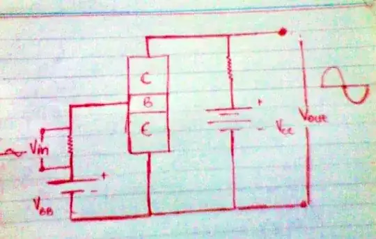
With that distinction made, we can look at your circuit and analyze the bias point, as Olin says, under "DC" conditions. Then we can superimpose on that the AC signal, so you have an "AC signal" with a "DC component". To recover just the AC signal, we discard all frequencies below some point.

Paradoxically, if we keep shrinking the range of frequencies that we consider as "AC" until the line is at 0Hz, you'd think now everything is AC and there is no DC. Yet, we then call everything DC, as in a "DC amplifier". I guess this is because it amplifies "everything down to DC", and people got lazy with their language.

Phil Frost
  • 56,804
  • 17
  • 141
  • 262
  • Don't forget about low amplitude signals. If you look at a DC voltage there will be lots of high frequency, but very, very low amplitude signals imposed on the DC (nanovolts and below much of the time). – reportingsjr Jan 24 '13 at 22:31