14

I am attempting to build a cat deterrent with an Arduino, something akin to this. I have figured out detection, and now realize that I need to use an ultrasonic transducer to produce the 'blast' that I need.

However, I am clueless as to how I would interface one of these with an arduino.

Does anyone have any advice?

Jonas
  • 187
  • 11
Michael Gorsuch
  • 251
  • 1
  • 2
  • 6

2 Answers2

9

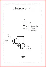
Since the Arduino pin won't be able to source enough current to drive the transducer very well, you can use a transistor with base connected to the Arduino pin to drive the transducer.

If we assume the transducer is a 40kHz (very common) one, then you would toggle the pin at 40kHz. Nice and simple.

Here are a couple of schematic options. The first one will probably work a bit better as it will develop a higher drive voltage (higher than the supply) due to the resonant circuit formed by the inductor and transducer capacitance.

Ultrasonic 1

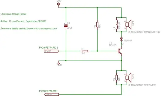
The reciever part in the above picture is not necessary for the cat deterrent project, this was taken from an ultrasonic range finder schematic where the echo needs to be timed. Unless you want know how close the cat is of course :-)

Ultrasonic 2

Oli Glaser
  • 54,990
  • 3
  • 76
  • 147
  • In the first diagram, what is the point of resistor R2? – Randomblue Feb 09 '13 at 12:14
  • @Randomblue - It looks like the designer wished to bias the transistor so it's slightly on without any drive from the micro (as opposed to cutoff or saturation) This would stop the transistor switching off completely when the drive voltage heads to 0V and limit the peak reverse voltage across the inductor. If you don't use an inductor in parallel then you don't need it (or the diode). – Oli Glaser Feb 09 '13 at 22:10
  • Depending on whether the transducer is some module or just a crystal, it might well need to be driven at resonant frequency, and not just on/off – Scott Seidman Jun 02 '13 at 14:49
4

Just looking at the ultrasonic transducer without having open one ever it looks like it ha similar functionality to a standard movement activated light. That means that in the top half of the transducer you see the lens which detects movement using a Passive infra red (PIR) sensor. When this detects any motion it switches a signal pin which triggers the ultrasonic burst. Of course you can take advantage of this and switch the signal pin using an arduino or any other microcontroller using your own cat detection method. Might be a good idea to put in a optocoupler between the arduino and the ultrasonic transducer to protect both circuits from each other.

here is some info about some optocoupler and I cant post the link about the pir since chiphacker dosnt trust me enough... But just go into arduino.cc and search for pir and you will find it

sjunnesson
  • 56
  • 2