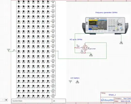
This really breaks down into two separate questions: Can you get LEDs which are fast enough, and can you drive them at this rate?.
Second part first - yes you can, but it's going to cost you. First, keep in mind that I'm assuming you're going for a nominal square wave in intensity. Second, 30 MHz is a total period of about 33 nsec, with about 16 nsec on and 16 nsec off. Third, as a rough number this implies that you want turn-on and turn-off times of about 5 nsec or less (1/3 of each phase's duration).
Can you do this? Yes, but not with your baseline setup. At the very least, the long wires implied by the schematic will cause all sorts of distortions to your drive currents, particularly ringing. If you really want to do this project, you are going to have to learn about low-frequency RF techniques, including cable termination.
Instead of a single driver, you'll need a distributed setup. Start with a choice of ICs. In this case, your best bet would be to go with a fast, high-current logic family such as the 74F series. This has the useful characteristic that they can be bought at places like Mouser.com. This will draw 15 mA per output (which is a good match for your 140 LED/ 2A total spec. Propagation delays, including rise and fall times, are a max of about 5 nsec, which again is a reasonable match. In this case, the 74F244, an 8-channel bus driver would seem like a good place to start. Alternatively, there are even faster logic families available, such as the 74FCT.
A first cut at the system would look something like

simulate this circuit – Schematic created using CircuitLab
Please note that ALL of the unused buffers actually get connected - I've just shown a single output for each of 3 levels. This approach will produce 144 outputs, each capable of a single LED.
Furthermore, the "LED" connection must look something like

simulate this circuit
R1 limits the ON current of the LED, and for a 74F244 and 5 volts drive, something like 120 to 150 ohms will limit the ON current to about 15 mA. R2 will pull about 1 mA through the LED when the buffer output is high. This means that the LED will never turn completely off, but it will considerably speed up the operation of the LED - and you'll need it. You can adjust R2, and increasing it will increase the on-off brightness ratio at the expense of speed. Depending on exactly what you're trying to do, you'll need to do some experimentation to try to get the tradeoffs you need. Be aware that, if the buffers are exceptionally good, they will be attempting to hold their outputs high enough that the LED won't turn on, and you'll have to decrease R2 to the point that LED turns on. This will be a matter of experimentation, and you might get lucky - but keep it in mind, since you might not.
Of course, you'll need a power supply rather than a battery, since the whole system will run off 5 volts rather than 12, but using a battery was never a good idea in the first place.
How much current will the supply need? Well, 2 amps or so for the LEDs. Plus the buffers. You'll need a total of about 20 chips, and about 2 amps for them, so count on a 5-amp supply.
Now, about LEDs. I do hope you're not figuring to use something cheap and readily available. Most LEDs aren't rated for switching speed, and those that are are expensive and (in this case) pretty marginal. Go to Digikey.com and search for LED emitters, then refine the search to IR LEDs, and start looking for units which do specify switching time. I found 3 (all with a maximum current of 20 mA), and they all had combined switching times (on to off and off to on) of about 25 - 30 nsec. Because of R2 in my LED circuit, the LEDs will do somewhat better than that - they never turn completely off - so let's assume that any of them will work. You would need to test them, of course, but let's be optimistic. The cheapest https://media.digikey.com/pdf/Data%20Sheets/Photonic%20Detetectors%20Inc%20PDFs/LS-0730-XX.pdf is $9 each and they only have 30 in stock. Ordering 140 will surely get you a price break, but you're going to have to wait a while. Is $1000 or so in your budget? If you can't wait, there's another unit with 97 available, but they run $27 apiece.
You are, of course, free to build a single driver channel and start buying various IR LEDs in small quantity and testing them, hoping to find a model which has the speed you need. Good luck.
Oh yes, and you DO have an optical sensor which will operate out to 100 MHz or so, so you can check to see that your array is working as intended, right? If not, Thorlabs will sell you just what you need https://www.thorlabs.com/thorproduct.cfm?partnumber=DET10A2#ad-image-0
Finally, you can build all of your drivers/LEDs on a single printed circuit board, and you'd be well-advised to do this. It will be a big (and therefore expensive) board and you should count on at least 12 x 12 inches. You may be able to get clever and modularize your setup so as to use a larger number of smaller boards, but that's up to you. It will also increase the number of kinds of boards you use, and this will increase cost. You'll want to lay out your circuit so as to keep all the lead lengths, especially the LED current paths, as short as possible. You'll need a decent ground plane and very good decoupling (not to mention RF shielding) since you'll be drawing 2 amps at 30 MHz, and unless you're careful you'll run into problems with ground currents - not to mention RF interference/radiation issues due to the current input. You may be able to get away with a 2-layer board, but only if you know what you're doing. Running power from your supply to the board via twisted pair will probably be adequate - but then again it may not, depending on what other equipment/sensors you have operating in your lab. I requested that you provide much more detail about what you're doing (and you've ignored it so far), and I wasn't asking out of idle curiosity.


